Civil Engineering Reference
In-Depth Information
2
2
4
4
17 cm
5
7
2.5
2.5
7
5
60 cm
R
= 17 cm
5
5
60 cm
5
5
2
16.5
16.5
80 cm
15
3327.2 kN
544.15 kN
1590 kN
10
30.0
15 cm
30.0
10
10
90 cm
10
s
1
s
1
7.5
Socket
Socket
s
y
1
0
40.0 cm
40.0 cm
15
x
x
90
80
10
s
y
-
f
min
= 0.19 MPa
3.65 MPa
f
max
= 6.17 MPa
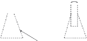
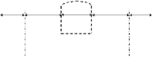
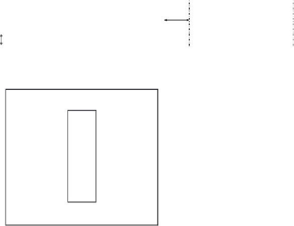
Figure 4.34 Detailing of the hinged line rocker fabricated steel bridge bearings.
Q
lak
¼
33
L
a
,
b
¼
33
30
¼
990 kN
1000 kN
½
,
for Load Models 71
Q
lbk
¼
20
L
a
,
b
¼
20
30
¼
600
6000 kN
½
,
for Load Models 71,SW
=
0,SW
=
2 and HSLM
for the direction of the forces). Also, the reactions from upper and lower


Search WWH ::

Custom Search