Civil Engineering Reference
In-Depth Information
Q
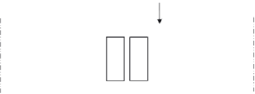
D+L+
f
= 599.5 kN
Q
D+L+
f
= 599.5 kN
N
1
N
2
Figure 4.29 The connection between stringer and cross girder.
Then,
F
v,Rd
equals 176 kN (for bolts in single shear) and 353 kN (for bolts
in double shear):
k
s
nm
g
M3
F
p
,
C
F
s
,
Rd
¼
F
p
,
C
¼
0
:
7
f
ub
A
s
¼
0
:
7
800
573
¼
320,880N
1
:
0
1
:
0
0
:
4
F
s
,
Rd
,
ser
¼
320,880
¼
116,683
:
6N
:
1
:
1
Then,
F
s,Rd
¼
117 kN (for bolts in single shear at serviceability limit
states) and
F
s,Rd
¼
234 kN (for bolts in double shear at serviceability limit
states). At ultimate limit states,
F
s,Rd,ult
can be calculated as follows:
1
:
0
1
:
0
0
:
4
F
s
,
Rd
,
ult
¼
320,880
¼
102,682N
:
1
:
25
Then,
F
s,Rd
¼
103 kN (for bolts in single shear at ultimate limit states) and
F
s,Rd
¼
206 kN (for bolts in double shear at ultimate limit states):
599
5
206
¼
2
:
N
1
¼
:
9 taken as 3 bolts,
:
599
5
103
¼
5
N
2
¼
:
8 taken as 6 bolts
4.2.11 Design of Cross Girder-Main Plate Girder connection
The cross girder is designed as a simply supported beam on main plate
girders; therefore, once again, the connection is mainly transferring
shear forces (maximum reaction from cross girders of 1502.7 kN) (see
Figure 4.30
)
. We can determine the required number of bolts as follows:


Search WWH ::

Custom Search