Civil Engineering Reference
In-Depth Information
Considering the structural analysis for the upper wind bracing system
shown in
Figure 4.26
,
the critical design wind force in the diagonal bracing
members can be calculated as follows:
Distributed wind loads
ðq
WL
Þ¼
522
:
6
5
ð
:
5
=
7
Þ=
30
¼
13
:
69 kN
=
m
Factored distributed wind loads
¼ q
WL
g
q
¼
13
:
69
1
:
7
¼
23
:
27 kN
=
m
R
A
¼
100 + 23
:
27
15
¼
449
:
05 kN
a¼
tan
1
3
75
ð
:
6
=
5
Þ
35
:
F
D
¼
349
:
05
=
ð
2
sin35
:
75
Þ ¼
298
:
7kN
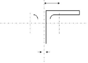
The cross section of the bracing member (see
Figure 4.28
) can be deter-
mined as follows:
2mm
Choose two angles back-to-back 150
150
15, with 10 mm gusset plate
between them:
l
b
x
¼
6160mm,
l
b
y
¼
1
:
2
6160
¼
739
:
4cm
2
,
A¼
2
43
:
2
¼
86
:
i
x
¼
4
:
59 cm,
e ¼
4
:
26 cm,
q
4
2
i
y
¼
:
59
2
+4
ð
:
=
Þ
¼
6
:
61 cm
26 + 1
2
r
235
275
e ¼
¼
0
:
924
L
cr
i
1
l
1
l¼
e
= 42.6 mm
y
x
x
2 angles back-to-back
150 × 150 × 15
10 mm
y
Figure 4.28 Upper wind bracing cross section s-s.


Search WWH ::

Custom Search