Civil Engineering Reference
In-Depth Information
Bending Moment Resistance
5
10
3
W
eff
,
min
f
y
g
M
0
68,379
:
275
M
c
,
Rd
¼
¼
¼
18,804,362,500Nmm
1
:
0
¼
18,804
:
4kNm
Length of Flange Plates
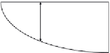
Assuming the overall bending moment diagram of the main plate girder
is a second-degree parabola (see
Figure 4.19
), we can determine the
length of the curtailed top flange plate of the upper and lower flanges
as follows:
2
x
24,032
18,804
:
4
5221
6
24,032
:
¼
¼
L
=
2
24,032
x
15
¼
0
:
466,
then
x¼
6
:
99m taken as 7m
:
Hence, the length of the smaller top plate is 14 m.
4.2.5 Design of the Fillet Weld Between Flange
Plates and Web
To determine the size of fillet weld connecting the bottom flange plates of
the upper and lower flanges with the web plate for the investigated bridge,
we can calculate the maximum shear flow at the support for the reduced
cross section, shown in
Figure 4.20
, as follows:
Inertia about
y
-
y¼
1.6
300
3
/12+2
[60
3
3
/12+60
3
151.5
2
]
¼
11,863,080 cm
4
.
18,804.4
D
x
m
15 m
Figure 4.19 Calculation of curtailed flange plate lengths.


Search WWH ::

Custom Search