Civil Engineering Reference
In-Depth Information
250 250
250 250 kN
Case of loading 1
q
vk
= 80 kN/m
q
vk
= 80 kN/m
A
B
12.6
11
0.8
1.6
1.6
1.6
0.8
30.0 m
I.L. for
B.M.D.
5.5
5.9
6.3
6.7
6.7
7.5
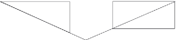
Figure 4.13 Determination of the maximum bendingmoment on one main plate girder
due to live loads using the influence line method (case of loading 1).
The first case of loading is that the centerline of the main plate girder is located
under one of the intermediate concentrated live loads, with maximum bend-
ing moment calculated at midspan (see
Figure 4.13
)
. On the other hand, the
second case of loading is that the centerline of a main plate girder divides the
spacing between the resultant of the concentrated live loads and the closest
load, with maximum bending moment located at the closest load (point a
in
Figure 4.14
). The maximum bending moment under the first case of load-
ing is calculated using the influence line method (by multiplying the concen-
trated loads by the companion coordinates on the bending moment diagram
and by multiplying the distributed loads by the companion areas on the bend-
ing moment diagram), while that under the second case of loading is calculated
250 250 250 250 kN
Case of loading 2
q
vk
= 80 kN/m
q
vk
= 80 kN/m
A
B
a
1.6
12.2
0.8
1.2
1.6
0.8
11.4
0.4
30.0 m
Y
A
= 1437.5 kN
Y
B
= 1450.5 kN
Figure 4.14 Determination of the maximum bendingmoment on one main plate girder
due to live loads using the analytical method (case of loading 2).


Search WWH ::

Custom Search