Civil Engineering Reference
In-Depth Information
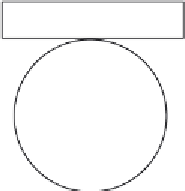
60°
45°
b
Figure 3.48 Load distribution to components according to BS EN 1337-4 [
3.12
].
at the extremes of movement determined in accordance with EN 1337-1
can be mounted at closer centers than circular rollers of the same load capac-
ity resulting in more compact bearings. Where a bearing has more than one
roller, an additional bearing in accordance with other parts of EN 1337 shall
be included to accommodate rotation (see
Figure 3.45
)
. The effects of any
rotation moments from this element shall be included when calculating the
roller forces by taking into account the corresponding eccentricities. The
load per roller shall be calculated at the extreme of the expected movement.
In addition, where a bearing has more than two rollers, the limiting values
for design load effects shall be taken as two-thirds of
N
0
Rd
. The design fric-
tion coefficient
m
d
shall be taken as 0.02 for steel with a hardness
300 HV
and 0.05 for all other steels.
Hinged line rocker bearings (see
Figure 3.46
)
are capable of transferring
applied vertical and horizontal forces between the superstructure and the
substructure. Hinged line rockers permit rotation in one direction about
the rocker axis. Hinged line rocker bearings resist horizontal forces by means
of positive mechanical restraint such as shear dowels. The design of rocker
rocker bearing is an inherent characteristic of the system based on its


Search WWH ::

Custom Search