Civil Engineering Reference
In-Depth Information
For pins subjected to combined shear and bending, the following inter-
action equation specified in EC3 (BS EN1993-1-8) [2.13] should be satisfied:
2
2
M
Ed
M
Rd
F
v
,
Ed
F
v
,
Rd
+
1
ð
3
:
121
Þ
where
d
is the diameter of the pin,
f
y
is the lower of the design strengths of
the pin and the connected part,
f
up
is the ultimate tensile strength of the pin,
f
yp
is the yield strength of the pin,
t
is the thickness of the connected part, and
A
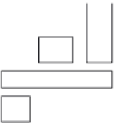
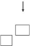
is the cross-sectional area of a pin. The moments in a pin should be cal-
culated on the basis that the connected parts form simple supports. It should
be generally assumed that the reactions between the pin and the connected
parts are uniformly distributed along the length in contact on each part as
indicated in
Figure 3.34
. If the pin is intended to be replaceable, the contact
bearing stress should satisfy
s
h
,
Ed
f
h
,
Rd
ð
3
:
122
Þ
r
EF
Ed
,
ser
d
0
d
ð
Þ
with,
s
h
,
Ed
¼
0
:
591
ð
3
:
123
Þ
d
2
t
0.5
F
Ed
0.5
F
Ed
b
d
o
d
a
c
c
a
F
Ed
F
M
=
Ed
(
b
+
4
c
+
2
a
)
Ed
8
Figure 3.34 Bending moment in a pin specified in EC3 (BS EN 1993-1-8) [2.13].


Search WWH ::

Custom Search