Civil Engineering Reference
In-Depth Information
≥
L
p
2
1.2
d
o
p
1
p
e
1
1
L
≥
2.4
d
o
e
2
p
p
2
2
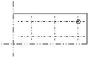
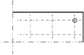
Staggered rows of fasteners
(a)
Symbols for spacing of fasteners
(b)
Symbols for staggered spacing
p
1
p
1,0
p
2
p
1,
i
p
≤
14
t
and
≤
200 mm
p
≤
14
t
and
≤
200 mm
p
≤
14
t
and
≤
200
p
i
≤
28
t
and
≤
400 mm
1
2
1,0
1,
(c)
(d)
Staggered spacing in compression members
Staggered spacing in tension members
e
4
d
o
e
3
0.5
d
o
End and edge distances for slotted holes
(e)
Figure 3.33 Symbols for end and edge distances and spacing of fasteners specified in
EC3 (BS EN 1993-1-8) [2.13].
F
v
,
Ed
F
t
,
Ed
F
v
,
Rd
+
4
F
t
,
Rd
1
:
0
ð
3
:
108
Þ
1
:
where
F
v,Ed
and
F
t,Ed
are the design shear and tensile forces per bolt for the
ultimate limit state, respectively.
EC3 (BS EN 1993-1-8) [2.13] also specifies design rules for preloaded
bolts. The design preload,
F
p,Cd
, to be used in design calculations should
be taken as
F
p
,
Cd
¼
0
:
7
f
ub
A
s
=
g
M7
ð
3
:
109
Þ
In single-lap joints with only one bolt row, the bolts should be provided
with washers under both the head and the nut. The design bearing resistance
F
b,Rd
for each bolt should be limited to


Search WWH ::

Custom Search