Civil Engineering Reference
In-Depth Information
2
4
1
3
b
1
b
0
b
eff
b
2
b
e1
b
0
b
e2
L
1
L
2
L
3
L
1
/4
L
1
/2
L
1
/4
L
2
/4
L
2
/2
L
2
/4
Key:
1
L
e
= 0.85
L
1
for
b
eff,1
2
L
e
= 0.25 (
L
1
+
L
2
)for
b
eff,2
3
L
e
= 0.70
L
2
for
b
eff,1
4
L
e
= 2
L
3
for
b
eff,2
b
eff,1
b
eff,1
b
eff,0
b
eff,2
b
eff,2
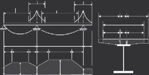
a constant effective width may be assumed over the whole of each span. This
value may be taken as the value
b
eff,1
at midspan for a span supported at both
ends or the value
b
eff,2
at the support for a cantilever. According to EC4
Figure 3.27
) may be determined as
b
eff
¼ b
o
+
X
b
ei
ð
3
:
69
Þ
where
b
0
is the distance between the centers of the outstand shear connectors
and
b
ei
is the value of the effective width of the concrete flange on each side
of the web and taken as
L
e
/8 (but not greater than the geometric width
b
i
).
The value
b
i
should be taken as the distance from the outstand shear connec-
tor to a point midway between adjacent webs, measured at middepth of the
concrete flange, except that at a free edge
b
i
is the distance to the free edge.
The length
L
e
should be taken as the approximate distance between points of
zero bending moment. For typical continuous composite beams, where a
moment envelope from various load arrangements governs the design,
The effective width at an end support may be determined as
b
eff
¼ b
o
+
X
b
i
b
ei
ð
3
:
70
Þ
71
Þ
where
b
ei
is the effective width of the end span at midspan and
L
e
is the
equivalent span of the end span according to
Figure 3.27
.
The distribution
of the effective width between supports and midspan regions may be
assumed as shown in
Figure 3.27
.
The transverse distribution of stresses
with
b
i
¼
0
ð
:
55 + 0
:
025
L
e
=
b
ei
Þ
1
:
0
ð
3
:
Search WWH ::

Custom Search