Civil Engineering Reference
In-Depth Information
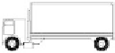
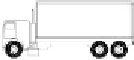
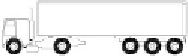
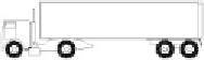
Table 3.7 Set of Frequent Motortrucks Specified in EC1 [
3.1
]
1
2
3
4
Axle spacing
(m)
Frequent axle loads
(kN)
Wheel type
(see
table 3.9
)
Motortruck silhouette
4.5
90
A
190
B
4.2
80
A
1.3
140
B
140
B
3.2
90
A
5.3
180
B
1.3
120
C
1.3
120
C
120
C
3.4
90
A
6.0
190
B
1.8
140
B
140
B
4.8
90
A
3.6
180
B
4.4
120
C
1.3
110
C
110
C
should be determined from the most severe effects of different motortrucks,
separately considered, traveling alone along the appropriate lane. Fatigue
Load Model 3 (single-vehicle model) consists of four axles, each of them
having two identical wheels. The geometry is shown in
Figure 3.14
. The
weight of each axle is equal to 120 kN, and the contact surface of each wheel
is a square of side 0.4 m. The maximum and minimum stresses and the stress
ranges for each cycle of stress fluctuation, that is, their algebraic difference,
resulting from the transit of the model along the bridge should be calculated.
Fatigue Load Model 4 (set of “standard” motortrucks) consists of sets of stan-
dard motortrucks, which together produce effects equivalent to those of typ-
ical traffic on European roads. A set of motortrucks appropriate to the traffic
mixes predicted for the route as defined in
Tables 3.7
and
3.8
should be
taken into account. Each standard motortruck is defined by the number
of axles and the axle spacing, the equivalent load of each axle, the wheel con-
tact areas, and the transverse distances between wheels. The calculations
should be based on the following procedure: the percentage of each standard


Search WWH ::

Custom Search