Environmental Engineering Reference
In-Depth Information
calculated in the numerical simulation, when the reef height is 7.5cm, the efficiency of the
reef unit performs best.
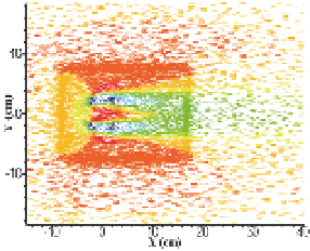
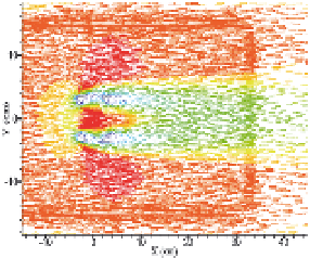
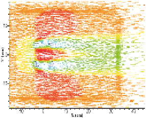
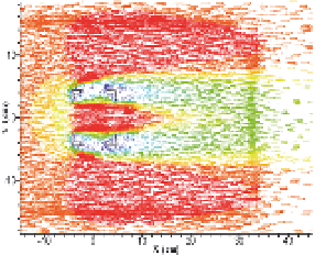
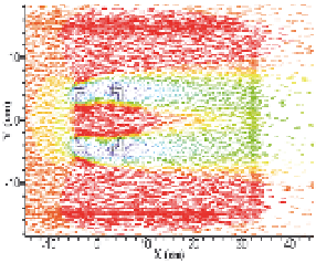
4.3 Flow field velocity vector diagram in the horizontal cross-section
The velocity vector diagrams in the horizontal cross-section that is located at the height of
1/2
h
are listed in Fig. 14. Similar structures of the flow field are obtained with different
heights of artificial reefs. Within the reef, the flow velocity is close to the inlet velocity. In the
area on either side of the artificial reef, the horizontal flow velocity is larger than the inlet
flow velocity, and the maximum values are 11.5, 11.9, 11.9, 12.3, 12.9 and 12.9 cm/s,
respectively, with increasing reef height. It is apparent that a higher artificial reef will have a
wider area in which the horizontal flow velocity is greater than the inlet velocity. The slow
flow field is distributed in the front and the back of the reef, where the structures of flow
fields vary with the reef height.
Fig. 14. Velocity vector diagrams in horizontal cross-section with different heights of
artificial reefs (the inlet velocity is 11.0 cm/s)


Search WWH ::

Custom Search