Geology Reference
In-Depth Information
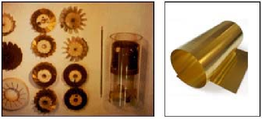
Figure 8.20.
Wind tunnel concepts for preliminary evaluation.
Figure 8.20 shows how simple aerodynamic concepts can be evaluated
using “shim stock” turbines that are easily fabricated. Since MWD blade pitch
angles range easily exceed 50 degrees, resulting in massive flow separation, the
details of the airfoil cross-section are secondary (high angles result from the use
of single, as opposed to multiple, turbine stages, a limitation imposed by
mechanical packaging constraints - without large pitch angles, the required
power cannot be achieved). Thus, simple blades cut from shim-stock (that is,
soft rolled-metal shown at the right) suffice for qualitative evaluation purposes.
Blades are easily trimmed, inserted and glued into balsa wood hubs; smooth
outer circular traces are obtained by turning down diameters to the desired size
in a lathe. The plastic tubular fixture shown is all that is required for stall torque
and no-load rotation rate measurement - Figure 8.18 gives the view from the
bottom of the test section in Figure 8.20. Once the effects of twist, blade
number, span and chord are determined for a particular configuration, more
precisely defined models can be constructed using computer-aided-design
(CAD) methods and 3D printing prototypes. This chapter offers only an
introduction to wind tunnel testing in MWD design. More sophisticated
techniques are given in Chapter 9 in the context of siren analysis, using modern
wind tunnels such as that shown in Figures 9-2a to 9-2h.
8.7 References
Hawthorne, W.R.,
Aerodynamics of Turbines and Compressors
, Volume X,
High Speed Aerodynamics and Jet Propulsion, Princeton University Press, 1964.
Oates, G.C.,
The Aerothermodynamics of Aircraft Gas Turbine Engines
, Air
Force Aero Propulsion Laboratory Report No. AFAPL-TR-78-52, July 1978.
Oates, G.C.,
Aerothermodynamics of Aircraft Engine Components, AIAA
Education Series,
American Institute of Aeronautics and Astronautics, New
York, 1985.

Search WWH ::

Custom Search