Geology Reference
In-Depth Information
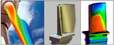
Figure 8.17c.
Blade twist, aerospace designs
(pressure variations in spanwise direction clearly evident).
Figure 8.17d.
Blade twist, downhole turbine concept.
Finally we emphasize that turbine jamming due to lost circulation material and
other downhole debris is a serious concern in operations. This can be assessed
from short wind tunnel analysis as described in the comments for Figure 9.3.
We note that a viable solution is offered in Gilbert and Tomek (1997) and the
reader is referred to their U.S. Patent 5,626,200 for further details.
8.6 Simplified Testing
The role played by wind tunnel analysis in MWD engineering, which is
further developed in Chapter 9, is very significant. Most striking is the
simplicity and low cost behind the evaluation techniques used. For example,
performance trends for our plastic unshrouded and shrouded turbines were
efficiently determined in the wind tunnel using the setup suggested in Figure
8.18, which provides a back view of the short wind tunnels described in Chapter
9 (here, wind is blowing out of the page). Recall that only two parameters,
namely, no-load rpm and stall torque, are required to determine both 'torque
versus rotation rate' and 'power versus rotation rate' performance maps
applicable to all fluids at all flow rates. To determine the no-load speed, a piece
of reflective adhesive tape is attached to the rearward face of the rotor; an
inexpensive optical tachometer is used to measure free-spinning rpm directly.
To measure stall torque, the arm of a linear force gauge is inserted through a
small hole drilled into the wind tunnel wall. The required stall torque is simply
the product of the measured force F and the moment arm R shown. Expensive

Search WWH ::

Custom Search