Geology Reference
In-Depth Information
8.5 Erosion and Power Evaluation
The results cited here apply to turbines in MWD tools and turbodrills
across a range of manufacturers. Turbine erosion and subsequent failure are
detrimental to MWD operations. There are two main erosion mechanisms,
namely, somewhat tolerable stator trailing edge erosion and more catastrophic
rotor tip erosion. The mud flow shown in Figure 8.1 first passes through the
stator row, which deflects oncoming fluid and allows it to impact rotor vanes
with greater force - this enhances torque and power creation. Since stator vanes
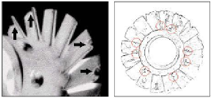
are attached to the shroud or housing, their tips cannot erode. The right
photograph in Figure 8.15 shows, however, that stator trailing edges can and do
erode; this occurs when small trapped rocks and debris induce local high
velocity jets that literally cut away metal where the blade joins the central
housing. Otherwise, stators undergo a sandpapering effect and erode slowly;
because they serve only to redirect flow, stator erosion is somewhat tolerable.
Figure 8.15.
Rotor tip erosion (left), stator trailing edge erosion (right).
Rotor tip clearances are required because drill collars bend and flex during
drilling operations. These clearances can be large, say, 0.1 inch, in order to
prevent the unacceptable jamming (and power loss) that arises from such
motions; sizeable clearances also reduce the likelihood of jamming by debris
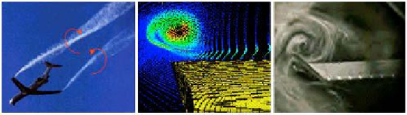
entrapment and mud gelling. Fluid movement from the high-pressure
undersides of rotor blades to the low-pressure upper-sides induces “tip vortex”
flows similar to those at airplane wing tips, as shown in Figure 8.16. These
angular momentum sources, by virtue of conservation laws well known in
physics, are difficult to dissipate.
Figure 8.16.
Tip vortex flows, high lift aircraft (left), computer simulation
(middle), and flow visualization (right).
Search WWH ::

Custom Search