Geology Reference
In-Depth Information
In designing an MWD turbine, one naturally turns, at first, to the wide
body of literature available in aerospace and mechanical engineering for
practical guidelines. However, MWD turbines are a special breed. To see why,
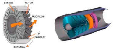
we examine typical aircraft turbines as shown in Figure 8.2. Since longitudinal
space constraints are not severe, such turbines are built with numerous stator-
rotor pairs. Thus, power generation is shared by multiple stages, and blade pitch
angles (required for torque and power production) need not be as highly inclined
as those for MWD - implying that inefficiencies due to flow separation are
avoided. To further enhance flow effectiveness, distances between blades are
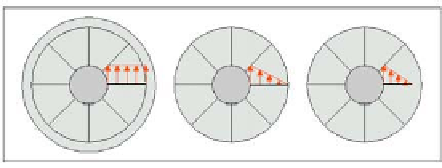
close. And finally, tip-to-housing clearances are vanishingly small - the left
diagram in Figure 8.3 shows that pressure loadings across the span of the rotor
blade are almost uniform, so that every part of the blade is effective in creating
torque and power.
Figures 8.1 and 8.2.
Single-stage MWD turbine versus multistage jet engine.
Figure 8.3.
Spanwise pressure loading as function of rotor tip clearance
(rotor tips do not support transverse pressure loadings).
As noted, MWD turbines must develop all the required power in a single
stage occupying just inches in the drill collar. Thus, blade pitch angles must be
high so that the flowing mud “pushes” as hard as possible. To make matters
worse, blade-to-blade separations cannot be small since debris entrapment may
lead to high localized erosion zones and even complete plugging of the tool.
These two effects significantly decrease turbine efficiencies since massive flow
separation is the rule. As if this were not enough, tip-to-housing clearances
cannot be small, since the slightest bend or transverse vibration in the drill collar
would jam the rotor and curtail power production. Sticking due to mud gelling
and debris entrapment is also a concern.
Search WWH ::

Custom Search