Geology Reference
In-Depth Information
U
f
D
U
f
U
f
tan D
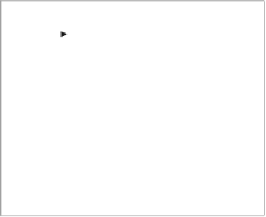
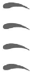
Figure 7.11.
Aerodynamic cascade problem.
In our approach, streamwise curvatures of upstream and downstream
annular spaces appear directly on the right-side of the equation. By contrast, the
mean R
m
on the left side contains the effects of hub radius, while individual
boundary conditions at R
i
and R
o
(to be described) implicitly include the effects
of the “siren lobe height,” that is, R
o
- R
i
. Hence, the two necessary length
scales R
m
and R
o
- R
i
appear as required in our three-dimensional formulation.
Although Figure 7.11 shows only single airfoil configurations, we emphasize
that standard formulations (outlined below) apply to “multi-element”
combinations as well, e.g., wings with trailing flaps, ailerons with control
structures, and so on.
7.3.5 Downstream flow deflection.
The theory underlying cascade analysis is summarized in the classic
turbomachinery topic of Hawthorne (1964) or in the comprehensive
aerodynamics topic of Oates (1978). Both give detailed derivations of
fundamental equations. The most relevant flow characteristic in studying single
and multi-element cascade flows is downstream streamline deflection. In
general, if a nonzero lift is exerted on the blade row, then the far downstream
flow must exhibit an exit angle deflection that is consistent with the momentum
theorem. For airfoil cascades, the deflection angle D in Figure 7.11 satisfies
tan D = ½ s
-1
³( |
I
l
|
2
- |
I
u
|
2
)/U
f
2
dx (7.3.12a)
following the nomenclature in Figure 7.4, where s is the vertical blade
separation between neighboring airfoils, and
l
and
u
denotes lower and upper
blade surfaces. The integral is taken from the upstream leading edge to the
downstream trailing edge. The deflection is independent of the density U and
the oncoming speed U
f
. The deflection of the downstream flow is associated
with a pressure drop
'p = ½ U
U
f
2
tan
2
D
(7.3.12b)


Search WWH ::

Custom Search