Geology Reference
In-Depth Information
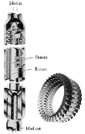
Figure 6.2b.
Turbodrill motors.
6.2.1 Positive displacement motors.
Downhole drilling motors, drawing hydraulic power from the flowing
mud, are used to turn the drillbit without turning the entire drillstring. Two
types are available, namely, the positive displacement drilling motors and
turbodrills represented, respectively, in Figures 6.2a and Figure 6.2b. In Figure
6.2a, downward flowing mud is forced through the cross-sectional space
between the metal (gray) rotor and the rubber (black) stator. This rotates the
spiraled rotor shaft which in turn drives the drillbit.
The MWD source, not shown in these figures, is positioned above the
drilling motor. When the pulser opens and shuts, it creates “intended signals”
that travel uphole (which embed the 0's and 1's position-encoded by valve
action), but as noted earlier in this topic, it creates equally strong signals of
opposite sign that travel downward. Chapter 4 assumes that the drillbit can be
modeled as a solid reflector or an acoustic open-end; these simple models
predict phases that are 180
o
apart, but in either case, signal shape remains
undistorted. Chapter 2 more generally treats the drillbit as one segment of a six-
segment waveguide, providing the needed transition between the two simpler
limits of Chapter 4. On the other hand, the previous section on desurger noise
demonstrates that not all reflections are so simple: those associated with elastic
boundary conditions at rubber interfaces may significantly distort MWD signals.
While the rubber reflector in our desurger is conveniently located at a
single point “x = 0,” the reflection in Figure 6.2a is distributed along the entire
length of the positive displacement motor. How MWD signals reflect will
Search WWH ::

Custom Search