Geology Reference
In-Depth Information
94
MWD Signal Analysis, Optimization and Design
p
3,solid
(x,t)/P
s
= i sin ZL
m
/c exp (+iZL
c
/c) / {(A
p
/A
c
) cos ZL
c
/c + i sin ZL
c
/c} e
iZ(t - x/c)
(3.B.16)
p
3,open
(x,t)/P
s
= - i cos ZL
m
/c exp (+iZL
c
/c)/ {(A
p
/A
c
) sin ZL
c
/c - i cos ZL
c
/c} e
iZ(t - x/c)
(3.B.17)
The quantity | P
3
(L
c
,t)/P
s
| provides a dimensionless measure of signal
optimization due to constructive wave interference. Recall that in an “infinite-
infinite” system without area change, a 'p pulse of strength p
s
splits into two
waves that travel in opposite directions having equal and opposite signal
strengths - ½ p
s
and + ½ p
s
. The complicated factors shown above represent
wave interference factors accounting for reflections at the drillbit and the collar-
pipe junction. The factors involve both amplitude and phase changes.
3.2.2 Example calculations.
Here we describe typical results and software capabilities. Our simulations
assume a drillpipe ID of 4 inches; an MWD drill collar having an ID of 6 inches,
an inner hub with a 3 inch diameter, and an axial length of 30 feet; a mud sound
speed of 4,000 ft/sec; and, finally, a maximum frequency of 300 Hz. Figures
3.B.2a to 3.B.2f display the MWD signal entering the drillpipe as a function of
source position in the collar and excitation frequency.
These displays are automatically generated - the entire process requires
seconds on personal computers. Results for “open” and “solid reflector” are
both computed. Dynamic views allowing rotation of the figures about various
axes and static views supporting contour plots are both supported. Again, the
following work assumes sinusoidal excitations whereas Chapters 4 and 5 allow
fully transient waveforms.
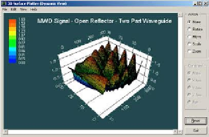
Case (e), two-part waveguide, open-ended reflector . . .
Figure 3.B.2a.
MWD signal, open reflector, dynamic rotatable view.
Search WWH ::

Custom Search