Geology Reference
In-Depth Information
2.5.3 Constructive interference at high frequencies.
We emphasize that a high drillpipe p/'p by itself will not guarantee higher
data rate. In the final analysis, the increase in starting pressure must offset any
frequency-dependent increase in attenuation over the drillpipe acoustic path.
But what are the limits of pressure optimization? The exact results for Figure
2.6 suggest that amplifications exceeding unity may be possible, but calculations
have never (until now) been undertaken for waveguides with the geometric
complexity of Figure 2.7. Are the increases 10%, 20% or more? With
expectations of only modest increases, this author ran the acoustic simulator,
each time only increasing the range of analysis frequencies incrementally. But
each time, optimistic results encouraged additional increases in the frequency
range. Again, the results obtained are exact and do not contain numerical
dissipation or phase errors typical of discretization schemes. Results for
drillpipe p/'p, plotted against pulser position and frequency, are offered next.
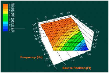
Figure 2.10a
. Drillpipe p/'p to 12 Hz.
Figure 2.10a again shows that, say at 1 Hz and below, source position is
not important and all signals are equally strong. The (red) transmission
efficiency is almost unity. In fact, a wave description of the problem is not
necessary. But at 12 Hz, destructive interference will reduce the carrier
frequency range available for MWD transmission if the pulser is not positioned
properly. The range of frequencies considered is increased to 24 Hz in Figure
2.10b. One clearly observes an intermediate band of frequencies for which the
transmission efficiency is low (highlighted in blue). However, near 24 Hz, a
transmission efficiency of unity is almost achieved for a narrow range of source
positions. Similar results are found in Figure 2.10c. In Figure 2.10d, the range
of frequencies studied increases to 75 Hz. At low frequencies near 1 Hz, the
transmission efficiency at all pulser locations is approximately unity as before,
although the color mapping is now green. Interestingly, high (red) transmission
efficiencies near
two
are now found for a limited band of frequencies greater
than 60 Hz for a range of pulser locations. Similar results are found in Figure
2.10e in which the frequency analysis range is increased to 100 Hz.
Search WWH ::

Custom Search