Image Processing Reference
In-Depth Information
The input image is transformed from its source space (e.g., sRGB)toL*a*b*
coordinates and then on to the CMYK space by using source and destination
pro
.
les. The destination pro
le is customized to the virtual printer model of
Figure 10.51.
The transformed image consisting of CMYK separations is halftoned using a
desired halftoning strategy.
.
The halftoned separations are exposed on the PR using a Gaussian or sinc
2
beam pro
.
le. This takes into account the dot gain due to laser spreading
effect at the microlevel. This has signi
cant effect on the perceived color of
the images.
Next the image consisting of four separations are passed through the dot
printer model. The output is the transferred mass density for each element
of the grid for each CMYK separation.
.
The mass density of four separations is used to generate L*a*b* values for
each pixel using standard color models.
.
The output image is transformed to the image source space (e.g., sRGB) and
displayed on the screen for evaluation purposes.
.
10.6 VIRTUAL PRINTER COLOR GAMUT
The color gamut for the virtual printer can be obtained using a series of color patches
spread over the CMYK space (Figure 10.52). The L*a*b* values for each of the
patches are obtained by averaging the patches. A comparison between the color
gamut of the virtual printer and a real printer is shown in Figure 10.53. The actual
available color gamut depends on the colorants of the pigments that are captured in
the toner master curves and other engine parameters like DMA, TMA, paper gloss,
etc. Since combinations of these parameters are not tuned to the actual printer shown
in Figure 10.53, the gamut volume, shape, and limits come out different. However,
this is not a trivial task (see Section 10.7), and requires careful design of experiments
and must be done in a laboratory environment. A comparison of color gamuts created
using the virtual printer can be seen in Figures 10.54 and 10.55. In Figure 10.54,
the solid gamut is created by using 9% TC for all the four separations while the
mesh gamut is created by using 12% TC for all the four separations. As a result of
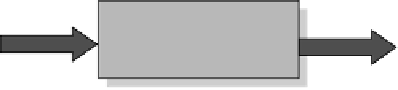
Input
color
patches
Virtual printer
model
Output averaged
L
*
a
*
b
* values
(Total number of color
evaluated—16
4
)
FIGURE 10.52
Schematic for obtaining the color gamut.


Search WWH ::

Custom Search