Image Processing Reference
In-Depth Information
(a)
Identity reference TRC
Reference TRC #2
(b)
(c)
Reference TRC #3
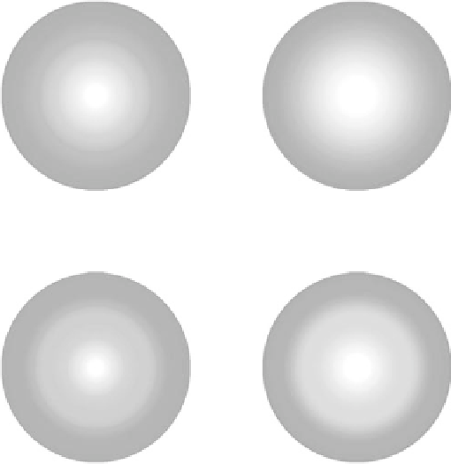
FIGURE 9.26
Circular cyan sweeps through the inverted TRC obtained for reference TRCs
and then through the printer model with output TRC shown in Figure 9.23. The images on the
right should match the images shown in Figure 9.24.
U
(
k
) ¼
U
0
þ
u
(
k
)
u
(
k
þ
) ¼
u
(
k
) þ
v
(
k
)
v
(
k
) ¼þ
Ke
(
k
)
1
(
9
:
49
)
where the vector, U
0
, contains the patch area coverages, U
1
, U
2
,
, U
N
, the error
...
vector, e(k)
¼
x
d
x(k), and x
d
is a column vector containing the desired tone values
r
1
,r
2
,..., r
N
, for the reference TRC at the patch area coverages. That is,


Search WWH ::

Custom Search