Image Processing Reference
In-Depth Information
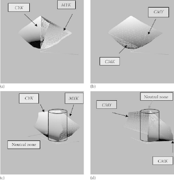
FIGURE 8.27
(a) CYK
!
L*a*b* and MYK
!
L*a*b* gamuts, (b) CMK
!
L*a*b* and
CMY
!
L*a*b* gamuts, (c) CYK
!
L*a*b* and MYK
!
L*a*b* gamuts (alternate view
shown with neutral zone), and (d) CMK
!
L*a*b* and CMY
!
L*a*b* gamuts (alternate
view shown with neutral zone).
(CMY
!
L*a*b*, MYK
!
L*a*b*, CYK
!
L*a*b*, and CMK
!
L*a*b*) and a
neutral zone.
Figure 8.27a through d shows in L*a*b* space for the four gamut classes,
CMY
!
L*a*b*, MYK
!
L*a*b*, CYK
!
L*a*b*, and CMK
!
L*a*b*,
respectively. The overall gamut is the union of all of them. In plots c and d,
Figure 8.27 shows an additional region classi
ed as the neutral zone. This approach
reduces the dimensionality of the four color process to three color groups. As a result
of this reduction, a three-input three-output MIMO control algorithm can be imple-
mented to achieve improved spot-color accuracy.
These gamut classes represent the color reproduction capability of a printer
obtained by considering three separations at a time. This can be a forward
printer model obtained via experimentation on a color printer or a mathematical
Search WWH ::

Custom Search