Image Processing Reference
In-Depth Information
250
SmoothTRC
Control patches
200
150
100
50
0
0
50
100
150
200
250
M
in
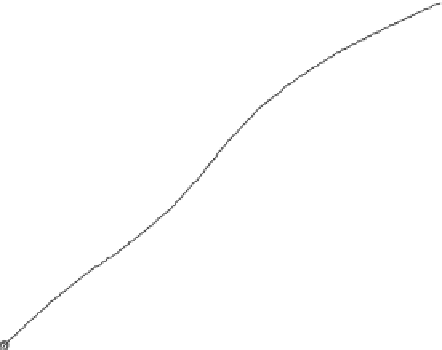
FIGURE 8.22
Magenta gray balanced TRC with highlight and shadow corrections for M
in
.
250
SmoothTRC
Control patches
200
150
100
50
0
0
50
100
150
200
250
Y
in
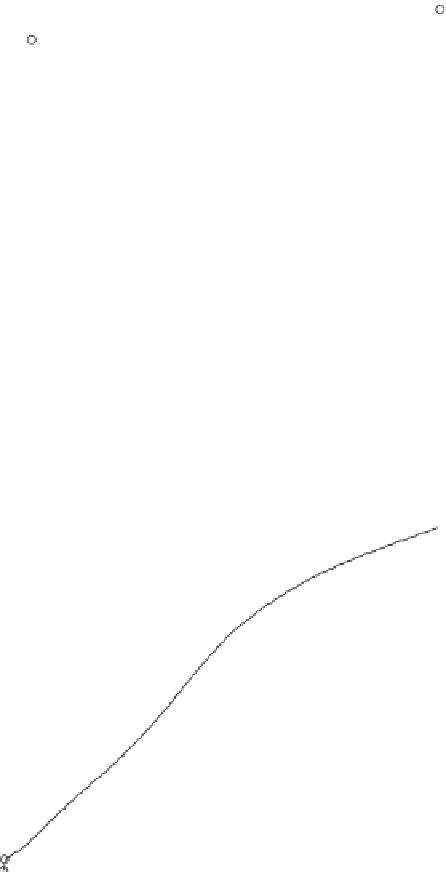
FIGURE 8.23
Yellow gray balanced TRC with highlight and shadow corrections for Y
in
.
prints along each of the ith axis of Figure 8.9. For example, N
1
grid points are placed
on the gray axis, N
2
points on the cyan primary axis, N
3
along secondary to black,
and so on. Once all these grid points are selected, N
1
N
2
N
3
, control loops
running in parallel are used to control all of them. The rest of the points in the plane
of Figure 8.9 are computed using a 2-D interpolation
=
smoothing algorithm. This
same process is repeated for all channels.


Search WWH ::

Custom Search