Image Processing Reference
In-Depth Information
Σ
CMYK
+
CMY
-
0.5
x
2
K
+
=x
2
x
2
CMY
-
x
CMY
-
= x
2
1
Min
K
+
x
Min (
C
,
M
,
Y
)
(a)
(b)
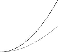
FIGURE 7.25
A simple GCR
=
UCR function (a) block diagram view (b) plot of GCR
function with respect to min (C, M, Y).
For example, CMY
¼
[0.5
0.3
0.4] color patch (CMY values in 0 to 1 range)
to CMYK
¼
is equivalent
[0.455
0.255
0.355
0.09] patch using the above
GCR
UCR algorithm. Soon it will become clear that this method has the disadvan-
tage of not producing suf
=
ciently optimized colors for the entire color gamut since
inherently the practice of starting with CMY separations and subsequently adding
black leads to loss of gamut. However, in Ref. [81] a max-gamut GCR is developed
which starts with CMY separations and still preserves the total gamut volume.
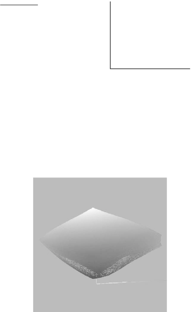
Figure 7.26 shows the comparison between the two gamuts; one gamut produced
FIGURE 7.26
CMYK gamut compared to a CMY to L*a*b* printer gamut with the simple
CMY to CMYK GCR (wire: A CMYK to L*a*b* gamut of a four-color printer; solid: a gamut
of a CMY to L*a*b* printer with GCR
=
UCR of Figure 7.25).


Search WWH ::

Custom Search