Java Reference
In-Depth Information
We want a simple diagram that displays requirements so that we can visualize
their relationships and dependencies. We first develop the diagram to be stand-
alone, and then we integrate it as a tab in the generated EMF editor to illustrate
the approach. Eventually, we want the requirements editor to be primarily form
based.
4.4.1 Diagram Definition
Beginning with the Graphical Definition Model Wizard, we create a new
requirements.gmfgraph
model in our
/diagrams
folder of the
org.eclipse.dsl.requirements
project. In the wizard, be sure to select the
Model
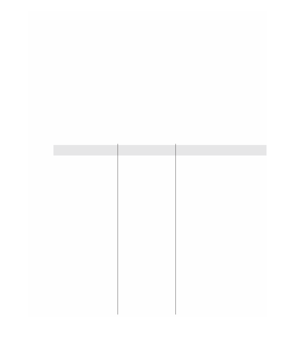
class as the diagram element. Table 4-11 shows the completed model,
indicating values that changed from their default.
Table 4-11
Requirements Figure Definition
Element
Property
Value
Canvas
Name
RequirementCanvas
Figure Gallery
Name
RequirementGallery
Polyline Decoration
Name
OpenArrow
Figure Descriptor
Name
Circle
Rectangle
Name
CircleOuterRectangle
Fill
False
Outline
False
Stack Layout
Ellipse
Name
Circle
Label
Name
CenterLetter
Basic Font
Face Name
Arial
Height
10
Style
BOLD
Margin Border
Insets
Left, Top
6, 5
Child Access
Figure
Rectangle CircleOuterRectangle


Search WWH ::

Custom Search