Information Technology Reference
In-Depth Information
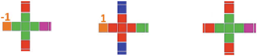
Fig. 6.
QCA majority gates, with and without one fixed input, and associated clocking.
The majority gates with cell polarizations fixed as
−
1 and +1 function as two-input
AND or OR gates, respectively.
The lower and upper bounds on the number of identically clocked cells in the
wire segments, which are based on considerations discussed in Refs. [
9
] and [
10
]
respectively, are selected to help ensure reliable information transfer. The min-
imum pitch is selected to minimize crosstalk from adjacent wires. The require-
ment of equal-length input and output legs in majority gates helps to ensure
simultaneous arrival of new inputs at the device cell, and thus fair voting [
9
].
We emphasize this simple set of design rules is presented for the purposes
of illustrating our modular dissipation analysis. Having said that, these simple
rules allow for construction of QCA circuits that implement any desired Boolean
function
3
and are generally consistent with common QCA design practice. It is
easily verified that the adder design of Fig.
2
adheres to these simple design rules.
Decomposition Rules.
Decomposition of a QCA circuit for modular analysis
requires that the circuit first be segmented into zones according to a design-rule-
specific set of decomposition rules. These rules stipulate how boundaries between
the zones are to be placed. For the set of example design rules presented above,
the decomposition rules are simply as follows:
1. Every cell in the circuit must belong to one and only one zone.
2. All zone boundaries must be placed
between
adjacent, identically clocked cells,
perpendicular to the direction of information flow. The same applies to the
boundary enclosing the full circuit.
3. Zone boundaries are to be placed between the two cells of the input legs and
between the two cells of the output legs of inverters, with no boundaries in
between.
4. Majority gates must be enclosed within a single zone as in Fig.
7
, i.e. with
zone boundaries placed so they enclose (a) the device cell and the identically
clocked, equal-length input and output legs, (b) one cell adjacent to each
input leg in the neighboring clock zone
4
, and (c) one cell adjacent to the
output leg in the neighboring clock zone.
3
AND, OR, and NOT form a universal set of primitives, and three-input majority
gates can implement two-input AND and OR functions if one if the inputs is appro-
priately biased as shown in Fig.
6
.
4
Alternatively, this cell could be fixed if the corresponding input is to be biased.
Search WWH ::

Custom Search