Information Technology Reference
In-Depth Information
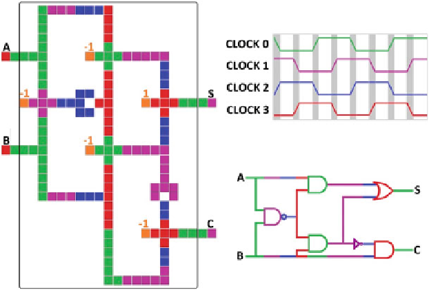
Fig. 2.
Cell layout, timing, and logic diagram for the Landauer-clocked QCA half adder
circuit used in this work to illustrate and compare general and modular dissipation
analyses.
of the adder. The two possible input bit values are assumed to occur with equal
probabilities for inputs
A
and
B
in these dissipation analyses, although uniform
input probabilities are not required by the formalism.
3.1 Analysis via General Approach
The initial step in applying the general approach is to construct the physical
abstraction of the circuit and its surroundings. Here the QCA adder is the infor-
mation processing artifact
, which holds
a physical instantiation of the string of two-bit inputs to be processed by the
adder, is included in
¯
A
of Fig.
1
. The input referent system
R
, as are the input and output cells
A
,
B
,
S
,and
C
.The
environmental domain includes the heat bath
A
at temperature
T
, which is in
direct thermal contact with the artifact, and the remote environmental subsys-
tems
B
¯
that “rethermalize” the bath when it is driven from a thermal state by
implementation of adder operations. The next step is to construct the process
abstraction. The four clock phases defined for Landauer clocking of the QCA
circuit - switch, hold, release and relax - are mapped onto the four physical
operations
φ
1
...φ
4
that act locally to implement computation over the
K
=11
steps of the computational cycle.
The final step in analysis via the general approach is the cost analysis. This
begins with identification and assignment of data zones and data subzones, as
described in detail in our previous work [
3
,
5
]. This can be quite involved even
for relatively simple circuits. For the adder circuit of the present work, the data
zones and subzones are
B
Search WWH ::

Custom Search