Information Technology Reference
In-Depth Information
the charge distribution inside a bis-ferrocene molecule (MUT) in presence of a
driver, for different positions of the driver (ideal and subject to a defect).
Figure
34
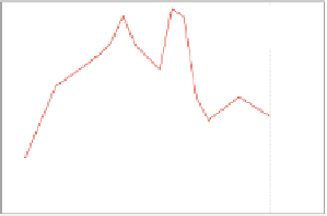
displays the results for the driver shifting along the vertical axes,
defined as Z-displ. The graph includes the results for three different distances
from the MUT (equivalent to three values of Y-displ), considering the driver in
both the logic state. The charge difference between the two dots of the MUT
decreases when the value of Z-displ is increased, which is enhanced for longer
distances from the molecule (higher Y-displ). In particular, in the range related
to the roughness of each grain of the gold substrate (
0
.
4 nm) the molecule
still works properly, that means that the free positive charge is mainly localized
on one of the two dots, encoding a valid logic state. On the contrary, when the
driver-MUT interaction is at the interface between two gold grains (equivalent
to
Z
-
displ
=
±
0
.
2
÷
2
.
0 nm) the molecule is in an undefined state, because the charge
of the two dots is almost the same.
±
Driver @ ''0'' - deltaZ, deltaY (d)
Driver @ logic ''1''
0.9
0.9
Y-displ = -0.20 nm
Y-displ = 0 nm
Y-displ = +0.25 nm
Y-displ = -0.20 nm
Y-displ = 0 nm
Y
-displ = +0.25 nm
0.8
0.8
Dot 1
Dot 2
0.7
0.7
0.6
0.6
0.5
0.5
0.4
0.4
0.3
0.3
Dot 2
Dot 1
0.2
0.2
0.1
0.1
0
0
-2
-1.5
-1
-0.5
0
0.5
1
1.5
2
-2
-1.5
-1
-0.5
0
0.5
1
1.5
2
Z-displacement [nm]
Z-displacement [nm]
Fig. 34.
MUT dot charges as function of the driver vertical shifting (Z-displ), in three
case of driver-molecule distance (Y-displ).
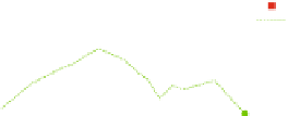
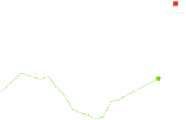
For what concerns the driver misalignment with the respect to the two dots
of the MUT (X-displ), the dot charges are reported in Fig.
35
for the ideal
distance between the MUT and the driver (Y-displ = 0) and two other cases of
driver-molecule distance (Y-displ =
0
.
20 nm and Y-displ = +0
.
25 nm). In these
graphs, both the driver logic states at 1 and at 0 are reported simultaneously, in
order to check immediately the MUT capability to encode the binary information
for a specific driver position. In particular, for a given X-displ value it is possible
to check if the positive charge inside the MUT moves between the two dots
when the driver changes its state from 1 to 0 and the difference between them
is large enough to consider the MUT in a valid logic state. Figure
35
reveals
that in some cases of driver misalignment the interaction with the MUT is still
preserved.
Finally, the simultaneous concurrency of driver and receiver defects were
analyzed in order to draw a Safe Operating Area (SOA), that shows all the
positions of the receiver that do not prevent the communication among the
molecules. The results are reported in Fig.
36
, where different corner cases of
−


Search WWH ::

Custom Search