Information Technology Reference
In-Depth Information
Bis-ferrocene charges: Dot1, Dot2, Dot3
1.2
1
0.8
0.6
Dot1
Dot2
Dot3
0.4
0.2
0
-0.2
-6
-4
-2
0
2
4
6
Electric Field [V/nm]
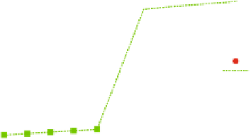
Fig. 24.
Oxidized bis-ferrocene molecule: dot charges as function of the switching field.
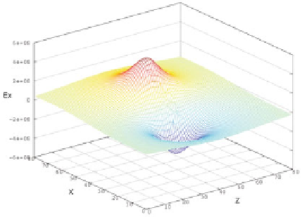
Fig. 25.
X component of the electric field generated by the bis-ferrocene at the equi-
librium and measured at a distance of 1.0 nm from the molecule.
In the same way, the electric field generated by the molecule under the effect
of a switching field was computed, and in order to evaluate the actual effect on
an ideal receiver, it is necessary to cut the curves along the axis where the active
dots of the receiver stand, that means fixing the position of the receiver on the
Z axis since the active dots of both the molecule and the receiver lie along the X
direction. Figure
26
shows the results for the molecule at the equilibrium (SW-
Field = 0, red line) and in two cases of switching field (SW-Field =
0
.
5nm
and SW-Field = +0
.
5 nm, respectively blue and green line). The two vertical
violet lines indicate the width of the receiver, that is equal to 1.0 nm (the width
of a bis-ferrocene molecule). In order to evaluate the effects of the electric field
on the receiver, the curves have to be considered only along the receiver width.
At the equilibrium (red curve) the two dots of the receiver (placed at the edge
−


Search WWH ::

Custom Search