Information Technology Reference
In-Depth Information
direction. However, when this field is removed, the dots will ''snap'' back into the
preferred ''up'' or ''down'' easy-axis direction, and the fringing fields from the
neighbors can bias which way they switch. This switching field acts as a magnetic
clock.
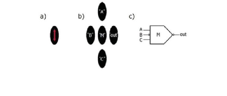
It turns out that the ''native'' logic element for NML is a three-input majority-logic
gate, just like for the original electronic QCA. As shown schematically below, this
gate consists of a cross-shaped arrangement of five dots, where three of the arms
(labeled ''A,'' ''B,'' and ''C'') represent the inputs, the center dot (labeled ''M'')
calculates the majority vote of these inputs, and the fourth arm (labeled ''out'') rep-
resents the output. This arrangement can also be viewed as the intersection between an
antiferromagnetic and a ferromagnetic wire segment. Note that the majority vote is
''calculated'' through magnetic interactions in this physics-driven NML computing
scheme (Fig.
3
).
It is interesting to note that such a three-input majority gate can be reduced to either
a binary AND or OR gate by viewing one of the inputs as a set-input, which selects the
functionality of the gate. For example, if we view ''C'' as the set-input, and ''A'' and
''B'' as the data inputs, then a ''0'' on ''C'' means that both ''A'' and ''B'' have to be
''1'' in order to have a majority vote of ''1'' at the output. In other words, setting ''C'' to
''0'' reduces the three-input majority gate to an AND gate for the data inputs ''A'' and
''B.'' Conversely, setting ''C'' to ''1'' results in an OR gate since only either ''A'' or
''B'' have to be ''1'' in order to have a majority vote of ''1.'' This programmability
offers interesting possibilities from a computer science perspective since the func-
tionality of this gate can be determined by the current state of the computation.
We have experimentally demonstrated functioning majority-logic gates working
properly at room temperature [
13
]. The figure below [from the Science paper] shows
the eight possible input combinations for the three-input majority-logic gate. Note that
here the different input combinations were realized by different arrangements of the
horizontal input dots. However, the shape-dependent switching behavior of such
nanoscale magnets [
14
] can be exploited to individually address specific inputs, thus
providing programmability. We have since fabricated gates with input devices of
varying aspect ratios, which has allowed a single gate structure to be successfully
tested with all eight possible input combinations [
15
] (Fig.
4
).
Fig. 3. Schematic of a magnetic three-input majority-logic gate, which consists of a cross-
shaped arrangement of five dots. Panel (a) shows the basic dot, (b) the basic logic gate, and
(c) the logic-gate symbol.
Search WWH ::

Custom Search