Information Technology Reference
In-Depth Information
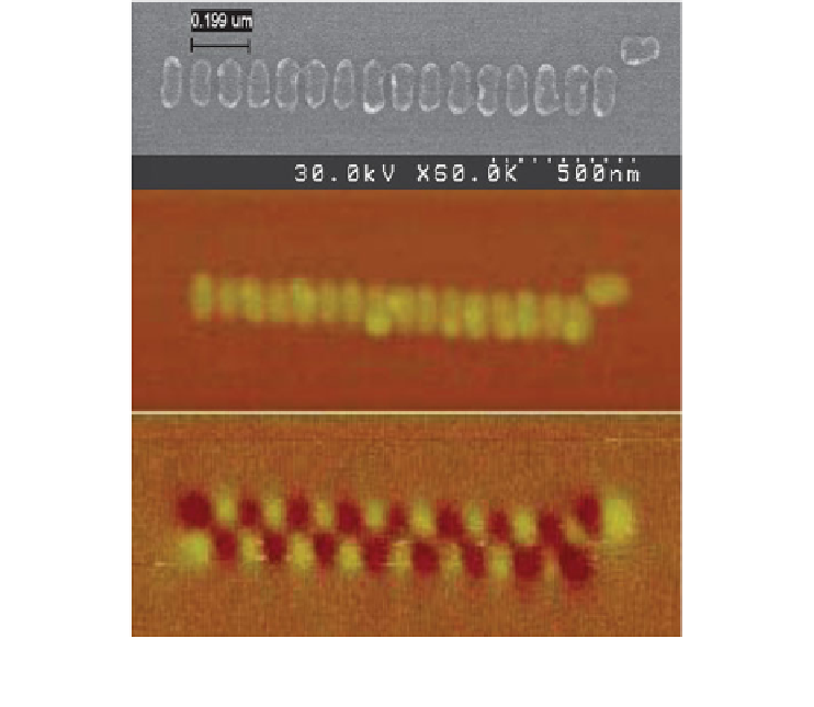
Fig. 2. Demonstration of a magnetically-ordered line of dots. Top panel: SEM, middle panel:
AFM, bottom panel: MFM.
this antiferromagnetic coupling. The other type of wire consists of the individual
magnets lined up in the same direction, and as one would expect, the individual
magnets also prefer to be magnetized in the same direction; we call this ferromagnetic
coupling.
Figure
2
shows an example of an antiferromagnetically-coupled wire consisting of
a chain of 16 dots. The top portion of the image shows an SEM (scanning electron
microscope) image of magnetic islands fabricated from a 30-nm thin film of permalloy
using electron beam lithography and standard lift-off techniques. The bottom portion
of the figure shows the structural AFM (atomic force microscope) image, and the
MFM (magnetic force microscope) image showing the magnetic contrast. The dot on
the top right (aligned in the horizontal direction) serves as an input that determines if
the wire is aligned up-down-up-down or down-up-down-up.
In these experiments, a magnetic field is required to aid the switching of the array
of nanomagnets [
12
]. When one dot is switched, the fringing fields are not sufficiently
strong to switch a neighboring magnet. However, the fringing fields can be used to
bias the switching event when an additional switching field is applied. Due to the
elongated shape (magnetic shape anisotropy), the dots have very stable magnetization
states along the long (magnetic easy) axis. They can be magnetized along the short
(magnetic hard) axis by the application of a sufficiently strong magnetic field in that
Search WWH ::

Custom Search