Information Technology Reference
In-Depth Information
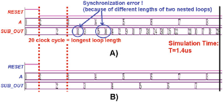
Fig. 19.
Simulation comparison with nested loops that have different (A) and equal
length (B). As can be observed, synchronization error will appear if the two nested
loop lengths are not equal.
The consequence is simple: if there are more loops inside the circuit and these
loops are nested inside each other, they must have the same length to obtain
perfect signals synchronization.
Additional Delay Loops.
The presence of loops introduces another problem
related to signal synchronization. Sometimes mapping an algorithm to an elec-
tronic circuit requires the insertion of a delay on specific signals. An example is
shown in Fig.
20
(A). An adder calculates the sum between a signal
A
, the same
signal delayed of an additional clock cycle
A
(
t −
1) and the output of the pre-
vious operation
1). When trying to map the same circuit onto NML
(or QCA) technology, one important problem arises. In the CMOS implementa-
tion the loop has a delay of exactly 1 clock cycle, a new input
A
is sent every
clock cycle. All signals arrive at the adder input with perfect synchronization,
respecting the algorithm.
However in NML (and QCA) loops normally have a delay of N clock cycles.
The result of the previous operation arrives at the adder input after N clock
cycles. As explained in Sect.
3
a new data must be sent every N clock cycles.
This is true also in case of interleaving, because N operations are interleaved,
but the delay between one data and the subsequent data of the same opera-
tion is always N clock cycles. Therefore to map the same algorithm it is not
sucient to delay the input
A
by 1 clock cycle. It must be delayed by N
clock cycles (Fig.
20
(B)). Considering an example, an input (
a0
)issenttothe
first adder input. The output is calculated and after N clock cycles it reaches
the adder inputs. After N clock cycles a new data (
a1
) is sent to first adder
SUM
(
t −
Search WWH ::

Custom Search