Information Technology Reference
In-Depth Information
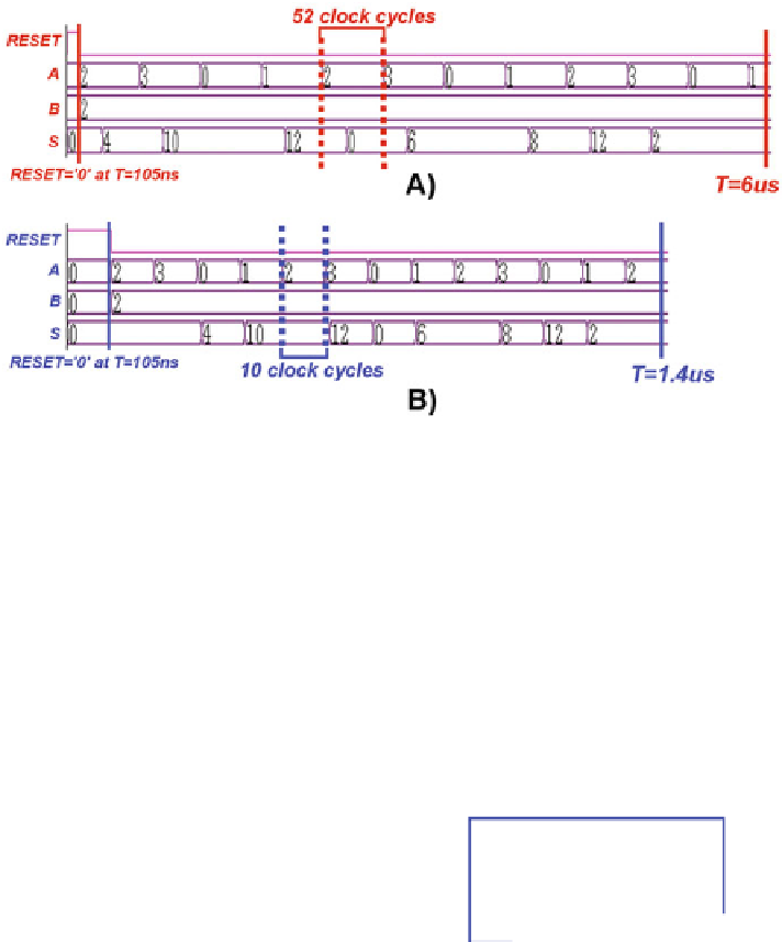
Fig. 17.
Simulation comparison between the original architecture (A) and the
redesigned architecture (B).
Nested Loops.
Generally, it is quite common to find multiple loops in a rela-
tively complex system, and they can be independent from each other or they can
be nested. In this second case, signal synchronization problems arise. A circuit
example with two nested loops is represented in Fig.
18
. The algorithm is simply
SUB OUT
=
SUM OUT − SUB IN
=
A
+
ADD IN − SUB IN
. Figure
19
shows instead the circuit simulation. Since
ADD IN
=
SUB IN
, the result is
simply the value of
A
.
B)
A)
REG0
REG0
L1
L1
REG1
REG1
L2
L2
SUB_IN
SUB_IN
SUB
(−)
SUB
(−)
SUB_OUT
SUB_OUT
5 ck
5 ck
ADD
(+)
ADD
(+)
ADD_IN
ADD_IN
SUM_OUT
SUM_OUT
5 ck
5 ck
A
A
L1
L2
L1
L2
Fig. 18.
Circuit representation with two nested loops (A). Originally, the two loops
L1 and L2 do not have the same length (B). For signal synchronization, loop L2 is
extended to the same length as loop L1.
If the loop lengths are different (Fig.
18
(A)) signals are not perfectly syn-
chronized and the output result is wrong as can be observed from Fig.
19
(A).
If the loop lengths are equal (Fig.
18
(B)) the circuit output is correct, as the
simulation of Fig.
19
(B) clearly demonstrates.


Search WWH ::

Custom Search