Information Technology Reference
In-Depth Information
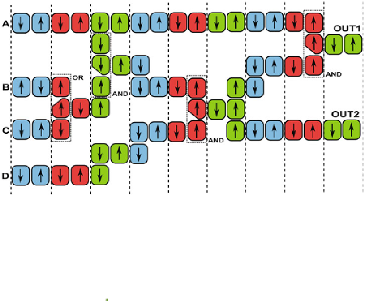
Fig. 11.
Regular clock zones layout to obtain automatic signals synchronization. Clock
zones are made by parallel strips, input comes from left direction while outputs are
generated at the circuit right side.
MULTIPLIER
ADDER
A
IN1
*
R
E
G
B
+
F
F'
IN2
MAC
F = (A*B)+F'
Loop = 52
clock cycles
LOOP
Fig. 12.
NML 2 bits Multiply and accumulate unit layout. (A) Detailed circuit layout.
The loop length is 52 clock cycles. In the upper detail
throughput of N times. To demonstrate this fact the MAC unit was described
using the VHDL model outlined in Sect.
2.1
. Simulation results are reported in
Fig.
13
. The loop length is 52 clock cycles, so if inputs are fed to the circuit
one every 52 clock cycles the MAC output is correct (Fig.
13
(A)). If the delay
between subsequent data is lower, for example 50 clock cycles like in Fig.
13
(B),
errors are generated. This behavior can be easily explained by the fact that once
the multiplication output is generated it needs 52 clock cycles to travel back and
to reach the adder inputs. Therefore to synchronize signals the next output of the
multiplier must be generated exactly with a delay of 52 clock cycles, in this way
it will reach the adder input together with the previously generated multiplier
output. This is a common problem also in CMOS technology, for example in
superscalar microprocessors. However in this case the level of pipelining is much


Search WWH ::

Custom Search