Information Technology Reference
In-Depth Information
BL
M4
STT-MRAM Array
Free Layer
Fixed Layer
BL
Sense
Amp.
SL
M3
Write
Dr.
M2
Via
WL
SL
M1
WL
Access
Transistor
Addr.
Buff
Column Decoder
BL : Bit Line; SL : Source Line; WL : Word Line
(a)
(b)
Fig. 3.
(a) STT-MRAM architecture; (b) An example of STT-MRAM bit cross-section
and CMOS integration. M1, M2, M3 and M4 are the metal layers 1, 2, 3 and 4
respectively.
between closely spaced nanomagnets was used to propagate information. The
first logic computation using nanomagnets was first demonstrated by researchers
from University of Notre Dame in 2006 [
6
]. In their work, the researchers once
again used magnetostatic interaction between closely placed nanomagnets for
computation. However, this time the nanomagnetic dots were elongated to give
them a shape anisotropy. The function of shape anisotropy is to define two stable
magnetic states at room temperature. This preferred magnetization direction is
also called the easy axis and is used to represent the logic 0 and 1 states (see
Fig.
4
a, where the easy axis is along the
y
direction for the nanomagnets).
B
y
Y
2
x
Y
0
A
Clocked
Y
1
L
0
L
1
Y
3
→
→
C
0
∏/2
∏
→
Relative magnetization (M) w.r.t. y-axis
(a)
(b)
(c)
(d)
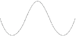
Fig. 4.
(a) Logic 0 and 1 states along with clocked configuration in single layer sin-
gle domain nanomagnets with shape anisotropy; (b) Majority voter.
A
,
B
and
C
are
inputs and
Y
is the output.
Y
=
A · B
+
B · C
+
C · A
; (c) Ferromagnetic coupling;
(d) Antiferromagnetic coupling.


Search WWH ::

Custom Search