Information Technology Reference
In-Depth Information
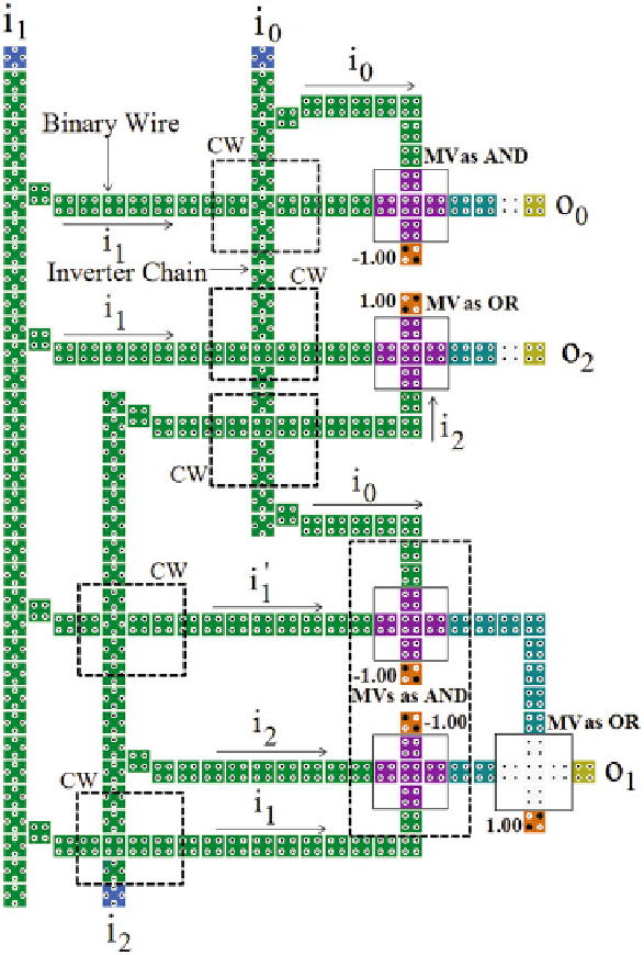
Fig. 23.
QCA layout of MX-qca gate. CW represents cross wire resulted from inter-
section of binary wire and inverter chain, MV represents majority voter
vectors is shown in Fig.
25
. The shaded devices in the Fig.
25
represent their
fault tolerant counterparts. Thus, conservative logic QCA circuits based on the
QCA layout of the Mx-cqca gate illustrated in Fig.
25
, can be tested by all 0s
and all 1s test vectors for presence of single missing/additional cell defect.
Search WWH ::

Custom Search