Environmental Engineering Reference
In-Depth Information
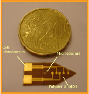
Fig. 8.4 Planar polymer
microchip for ESI produced
by DiagnoSwiss (courtesy
of DiagnoSwiss)
fragmentation of labile groups attached to the main structural backbone is mini-
mized, enhancing the sensitivity of the analysis.
Another popular category of chips for ESI MS consists of planar or thin
microchips, made from glass [
28
] or polymer [
29
] material, embedding a
microchannel at the end of which electrospray is generated in-plane, on the edge
of the microchip.
During the last years, the progress in polymer-based microsprayer systems was
promoted by development of simpler methods for accurate plastic replications and
ease to create lower-cost disposable chips. For instance, DiagnoSwiss Lausanne has
developed a disposable polymer microchip with integrated microchannels and
electrodes, which was coupled to both a quadrupole time-of-flight and a Fourier
transform ion cyclotron resonances mass spectrometer [
30
]. The chip presented in
Fig.
8.4
was microfabricated
by
semiconductor
techniques
including
photolithography [
30
].
For the microchip fabrication, the starting material was a polyimide foil of
75 mm thickness, which is coated on both sides with 5 mm copper. A photoresist
was patterned on the copper-coated polyimide foil through a printed slide acting as
a mask. Photoresist was then developed and chemical etching was used to remove
the deprotected copper where microchannels are to be patterned. Polyimide was
plasma-etched to the desired depth. As both sides of the substrate were exposed to
the plasma, through-holes were fabricated to act as sample reservoirs and/or
provide access to the microchannel. The final microchannels were 120 mm wide,
45 mm deep (nearly “half moon” cross section), with 100 mm gold-coated micro-
electrodes placed at the bottom of the microchannel (Fig.
8.5
).
A 35 mm polyethylene/polyethylene terephthalate was laminated to close the
channels. As described before [
30
] one end of each channel was manually cut in a
tip shape, so that the outlet of the microchannel was located on the edge of the chip.
For sample dispensing, either a reservoir was pasted over the inlet of the
microchannel or the chip was sandwiched in a home-made chip holder with an
integrated reservoir (Fig.
8.6
).