Environmental Engineering Reference
In-Depth Information
(a)
(b)
Effluent
Effluent
Anode (graphite rods)
Air
Cathode (carbon/Pt catalyst)
Resistance
PEM
PEM
Influent
Granular
anode
Graphite
cath
ode
(c)
Sampling
port
Anode
cover
Cathode
Anode
Influent
Chamber
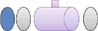
Fig. 18.3 Schematics of typical single-chamber MFCs: a The first SCMFC for domestic
wastewater treatment; b Tubular MFC; c a lab-scale single-chamber MFC
Liu et al. (
2004
) first demonstrated that domestic wastewater could be used as
the substrate in MFCs without actively feeding air into a cathode chamber. Their
MFC consisted of a single chamber with eight graphite electrodes (anodes) and a
single air cathode as shown in Fig.
18.3
a. Most importantly, the promising idea of
using MFC technology to reduce energy costs in wastewater treatment was initi-
ated. A tubular MFC (TMFC), designed by Rebeay and colleagues (Rabaey et al.
2005b
) was shown in Fig.
18.3
b. The TMFC had a wet anode volume of 210 mL
and generated a maximum volumetric power of 90 W/m
3
using graphite granules
as the anode and a ferricyanide solution in the cathode chamber. A relatively low
internal resistance of 4 X was achieved by sustaining a short distance between the
anode and cathode electrodes and a large PEM surface area. Rabaey et al. (
2005b
)
believed that the use of sustainable open air cathodes was a promising design for
practical implementation.
It has been demonstrated that power output can further be increased in a single-
chamber MFC by removing the PEM. Liu et al. (
2004
) found that there was a
significant rise in power density by a factor of approximately 1.9 for glucose and
5.2 for wastewater through removing the PEM from a single chamber MFC
(Fig.
18.3
c). This increase was partly attributed to an enhancement of the proton
flux from the anode to the cathode. The lack of a PEM substantially reduce the


Search WWH ::

Custom Search