Graphics Reference
In-Depth Information
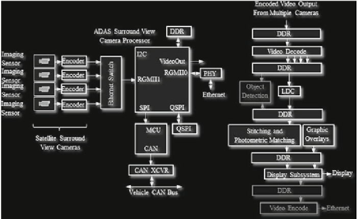
Fig. 3.5
Left panel
Block diagram of Ethernet-based surround view system;
Right panel
Simplified
data flow in Ethernet-based surround view system. Optional processing steps are shown in
light
shade of gray
Ethernet-based version of surround view system is presented in the left panel of
Fig.
3.5
. The satellite cameras, if needed, convert imaging sensor output from raw
format to YUV, and then compress the video frames by either using MJPEG or
H.264 before sending them via Ethernet to the central surround view processor. In
this case, Ethernet AVB protocol is used for synchronization of satellite cameras and
to minimize overall system latency. The compressed video streams from the satellite
camera are decoded on the central ECU.
Simplified data flow for the Ethernet-based surround view central processor is
shown on right panel of Fig.
3.5
. With exception of the very first step (video decode),
the data flow looks very similar to the one from LVDS-based surround view central
processor.
Video compression artifacts in the Ethernet-based system might influence perfor-
mance of the embedded vision algorithms. Some work is being done on assessing
impact of the video compression on night vision pedestrian detection [
9
], automotive
optical flow algorithms [
10
], and on stereo matching [
11
].
3.4 Key Components of Vision-Based ADAS
Powerful, energy-efficient systems-on-chip (SOC), along with low-cost wide
dynamic range imaging sensors, enabled the spread of embedded vision in ADAS.
Vision-based driver assistance systems require a variety of processors and image