Graphics Reference
In-Depth Information
Framelist
Feature extraction & matching
Ground removal
(Pixels bellow
height threshold)
if
|
T
|>
b
s, p
00
Rectification
Surface analysis
(Surface flat
enough and
no obstacles?)
s, p
-1
-1
s, p
-2
-2
Stereo Processing & 3D Reconstr.
Spatial analysis
(Does the
vehicle fit?)
s, p
-3
-3
distortion
removal
Landing map
Calculate Waypoints
waypoint 1
latest input
image
waypoint 2
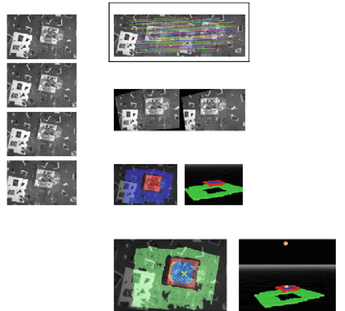
Fig. 4.17
Autonomous landing overview: New input images are stored in a frame list, together
with detected features, and camera poses. For selected image pairs, camera motion is estimated,
and the 3D model is determined. The result of the landing site detection is a landing map which
labels all pixels as:
green
(ground level),
red
(on rooftop but unsafe),
orange
(insufficient space),
or
blue
(safe landing area). The location with the highest confidence is labeled by
×
4.4.2.2 Landing Site Detection
After 3D reconstruction, the next step is to find potential landing candidates. We
define the following requirements for a suitable landing site: (a) A landing site has
to be planar, close to parallel to the ground plane, and free of obstacles and hazards,
(b) it has to be large enough to fit the MAV, and (c) it has to provide enough free
space around it for a safe approach.
To fulfill these requirements, we developed an efficient multistep algorithm which
uses the determined range data to reduce the problem to a basic probabilistic model.
Since our application is targeted to land on elevated surfaces for surveillance, we first
remove all candidates close to the ground level. Then we calculate the standard devi-
ation of the disparity map because the variance of the disparity map along the gravity