Information Technology Reference
In-Depth Information
n
0
,
n
2
overflow while
n
1
,
n
4
underflow.
Block
v
1,3
is moved from
n
0
to
n
4
and
block
v
1,4
is moved from
n
2
to
n
1
.
v
0,0
v
0,1
v
0,3
v
0,2
v
0,4
v
0,0
v
0,1
v
0,3
v
0,2
v
0,4
v
1,2
v
1,0
v
1,1
v
1,2
v
1,4
v
1,0
v
1,1
v
1,3
v
1,3
v
2,0
v
1,4
v
2,1
v
2,0
v
2,1
Re-organize
v
2,3
v
2,2
v
2,4
v
3,0
v
2,3
v
2,2
v
2,4
v
3,0
v
3,1
v
3,2
v
3,4
v
3,3
v
3,1
v
3,2
v
3,4
v
3,3
.
.
.
.
.
.
.
.
n
0
n
1
n
2
n
3
n
4
n
0
n
1
n
2
n
3
n
4
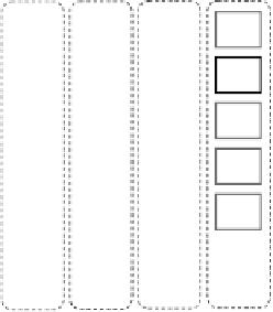
Group 1 before reorganization
Group 1 after reorganization
Figure 15.5
Reorganizing the second group of media data blocks
v
0,0
v
0,1
v
0,3
v
0,2
v
0,0
v
0,1
v
0,3
v
0,2
v
0,4
v
1,2
v
0,4
v
1,0
v
1,1
v
1,2
v
1,4
v
1,0
v
1,1
v
1,3
v
2,3
v
2,0
v
2,4
v
2,1
v
1,3
v
2,0
v
1,4
v
2,1
v
2,2
v
2,3
v
2,2
v
2,4
v
3,0
v
3,1
v
3,2
v
3,4
v
3,0
v
3,3
.
.
.
.
.
v
3,1
v
3,2
v
3,4
v
3,3
.
.
.
.
n
0
n
1
n
2
n
3
n
4
n
0
n
1
n
2
n
3
n
4
Before reorganization
After reorganization
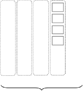
Figure 15.6
Reorganizing from4 to 5 nodes usingRPDR. Shadedmedia data blocks need to be relocated
to form the new configuration
streaming load balance we move block
v
1
,
3
from
n
0
to
n
4
and block
v
1
,
4
from
n
2
to
n
1
. Thus,
we need two block movements to reorganize this second group.
Repeating this process we can then reorganize the whole system. Figure 15.6 shows the
required block movements for the first four groups of media data blocks. Comparing it to
Figure 15.1, we can clearly see the savings in block movements (e.g., from 16 down to 5). In the


Search WWH ::

Custom Search