Information Technology Reference
In-Depth Information
Divides media data stream into fixed-size blocks
. . .
v
0,0
v
0,1
v
0,2
v
0,3
v
1,0
v
1,1
v
1,2
v
1,3
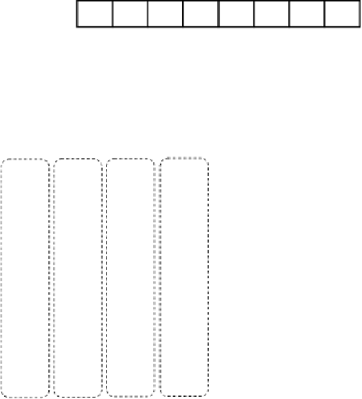
Round-robin Placement
Row-Permutated Placement
v
0,0
v
0,1
v
0,2
v
0,3
v
0,0
v
0,1
v
0,3
v
0,2
v
1,0
v
1,1
v
1,2
v
1,3
v
1,3
v
1,0
v
1,1
v
1,2
v
2,0
v
2,1
v
2,2
v
2,3
v
2,0
v
2,2
v
2,1
v
2,3
v
3,0
v
3,1
v
3,2
v
3,3
v
3,1
v
3,0
v
3,2
v
3,3
v
4,0
v
4,1
v
4,2
v
4,3
v
4,0
v
4,1
v
4,3
v
4,2
.
.
.
.
.
.
.
.
n
0
n
1
n
2
n
3
n
0
n
1
n
2
n
3
Figure 15.2
The row-permutated placement policy
}
will be distributed to all
N
nodes in pseudo-random order, with each node storing exactly
one of the
N
data blocks as shown in Figure 15.2. This process repeats for the next
N
data
blocks
Specifically, in a
N
-node system the first
N
media data blocks
{
v
0
,
j
|
j
=
0
,
1
,...,
N
−
1
, and so on until all data blocks are distributed. As long as
the client receives a whole parity group before decoding it for playback, this row-permutated
placement policy can achieve perfect streaming load balance, same as the original round-robin
placement policy.
{
v
1
,
j
|
j
=
0
,
1
,...,
N
−
1
}
15.3.2 Data Reorganization
To determine which data blocks will need to be moved after adding a new node, we first
re-index all the media data blocks according to the new configuration. Figure 15.3 shows an
example of reorganizing from a 4-node system to a 5-node system. For example, media blocks
v
1
,
0
and
v
1
,
0
respectively in the 5-node configuration.
If we consider the first group of media blocks in the new configuration, we can see that node
n
1
now needs to send two media blocks
v
1
,
1
will be re-indexed to
v
0
,
4
and
v
0
,
4
while the new node is not used. This is
the reason why load imbalance will occur if the data blocks are not reorganized.
v
0
,
1
and


Search WWH ::

Custom Search