Information Technology Reference
In-Depth Information
This could induce network congestion, leading to video packets being dropped at the network
switches and routers. Worse still, the client may not be able to cope with the aggregate data
rate even if the network can successfully deliver the data. To tackle this problem, we introduce
an over-rate transmission scheme that can effectively prevent traffic overlapping. To evaluate
the strengths and weaknesses of the proposed architecture, we use numerical results to com-
pare and contrast staggered-push architecture with the concurrent-push architecture covered
in Chapters 10 and 11 using the same system parameters and assumptions.
12.2 System Architecture
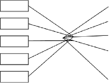
Figure 12.1 shows the architecture of a parallel video server, comprising multiple autonomous
servers connected by an interconnection network. We denote the number of servers in the
system by
N
S
and the number of clients by
N
C
. Hence the client-server ratio, denoted by
,
is
N
C
/
N
S
. Each server has separate CPU, memory, disk storage, and network interfaces. A
server's storage spaces are divided into fixed-size stripe units of
Q
bytes each. Each video title
is then striped into blocks of
Q
bytes and stored into the servers in a round-robin manner as
shown in Figure 12.1.
To schedule disk retrievals and network transmissions at the servers, we propose a
staggered-
push
algorithm where the servers transmit bursts of data to a client in a round-robin manner at
the average video bit-rate. Let
R
V
be the average video rate and assume it to be the same for all
clients. Then the transmissions from the servers are staggered so that only one of the servers
transmits to a receiver at any given time, depicted in Figure 12.2. In this way, there will be at
most
N
S
video blocks being transmitted concurrently at a server. Note that while one
can potentially reduce server buffer requirement by transmitting at a rate higher than
R
V
, the
client in turn will have to be capable of receiving at such a high data rate. This is less practical
as client network connection usually has lower bandwidth and the client device (e.g., set-top
box) will likely have limited processing capability.
To support staggered push, the server scheduler is divided into two scheduling levels:
micro-
round
and
macro-round
as shown in Figure 12.3. Video blocks retrieved in one micro-round
will be transmitted in the next micro-round. Let
T
F
be the average time needed to completely
transmit a video block of
Q
bytes. Since a video block is transmitted at a rate equal to the
=
N
C
/
. . .
v
0
v
5
v
10
Server S
0
Client C
0
Client C
1
. . .
v
1
v
6
v
11
Server S
1
Interconnection
Network
Client C
2
. . .
v
2
v
7
v
12
Server S
2
Client C
3
Stripe unit
. . .
v
3
v
8
v
13
Server S
3
.
. . .
Server S
4
v
4
v
9
v
14
Client C
N
C
−1
Figure 12.1
Architecture of a (5 servers) parallel video server


Search WWH ::

Custom Search