Geography Reference
In-Depth Information
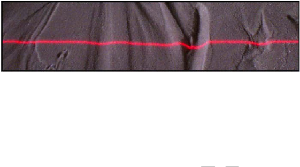
Figure 13.15
Example of a laser line (
∼
0.4 m) projected onto a sediment bed and photographed with a camera mounted at an
oblique angle (Tal, 2008).
uniform (free surface parallel to the bed surface), light
from the projector will bend normal to the surface and
will produce a bright spot when hitting the surface. From
the point of view of the camera, the bright spot is observed
in the direction corresponding to the angle
i
c
with respect
to the normal (Figure 13.19):
sin
i
p
sin
r
p
=
sin
i
c
sin
r
c
=
n
water
(13.4)
where
n
water
is the refractive index of water. The dif-
ference in elevation between the apparent location of the
bright spot (
h
) and the true depth (
H
) is obtained by
trigonometry:
(a)
(b)
tan
i
p
+
tan
i
c
tan
r
p
+
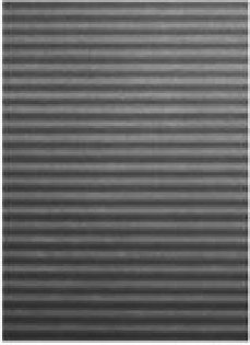
Figure 13.16
(a) Reference image (1 m long
5 m wide) of a
fringe pattern projected onto a flat bed and (b) a deformed
fringe pattern due to bed topography formed by braided
channels (Limare et al., 2011).
×
0
.
H
=
tan
r
p
h
(13.5)
The difference between topographies obtained with and
without flow will give a distorted bathymetry that is always
shallower than the true bathymetry and a correction
factor for the incidence angle needs to be applied. Inci-
dence angles can be calculated for any point using simple
trigonometry:
i
p
,
i
c
=
have a constant frequency across the experimental surface.
If the projector has a significant incidence angle (either
to project over a larger area or to reduce glare if water is
present), it may be necessary to compensate for this angle
when creating the grid to ensure a constant frequency
across the entire plane. In general, the moir´emethod
works well for light coloured, relatively uniform diffusive
substrate. As in the other imaging methods discussed,
glare should be reduced using polariser filters and sheets.
Images should be corrected for lens and perspective
distortion before any analysis.
A key advantage to the moire method is the ability
to estimate flow depths based on the refraction of light
at the air/water interface. Bed topography reconstructed
by any method based on grid deformation when water
is present on the bed will be distorted relative to bed
topography measured on a dry surface. This distortion
can be used to estimate flow depth from images acquired
with and without flow. Assuming the flow is locally
f
(
i
,
j
). In the case of parallel projec-
tion and observation beams, the relation between true and
distorted bathymetry has a simplified form:
H
=
n
water
h
.
A moire projection method was used to study the
evolution of microscale braided channels (Figure 13.20;
Limare et al., 2011). Experiments similar to the one here
are described in detail in Metivier and Meunier, (2003).
The experiments were conducted at the IPGP experimen-
tal geomorphology laboratory in a stream-table that was
1.5 m long and 0.75 m wide with a fully adjustable bed. The
initial slope of the bed was approximately 0.05. The sed-
iment in these experiments was composed of glass beads
with a D
50
of 250 micron and a density of 2500 kg/m
3
.
The initial condition for each experiment was a flat bed
with a straight channel (0.01 m deep and 0.02 m wide)
carved down the middle. The flow was laminar and a

Search WWH ::

Custom Search