Geography Reference
In-Depth Information
be visible in the imagery. In general, this is accomplished
by placing survey targets in the field area prior to image
acquisition. Alternatively, uniquely identifiable features
in the landscape such as man-made structures, boulders
or fallen trees can be used as control targets. This option
is especially attractive in the case of hyperspatial imagery
where individual landscape features are easily recognis-
able. These targets, either natural or man-made, then need
to be surveyed to high accuracy and therefore professional
geodetic GPS equipment is usually preferred. Once the
field data is collected, GIS or remote sensing software
must be used in order to georeference the imagery. This
usually involves the need for a user to manually identify
each GCP in each image. Clearly, such a manual approach
would be extremely labour intensive in the case of large
hyperspatial image databases.
Alternatively, the imagery can be georeferenced with-
out ground control points if the external orientation
(i.e. horizontal position, altitude above ground level and
orientation) of the camera is known at the time of expo-
sure. If we assume level ground, simple geometry can
be used to calculate the position of the image. However,
this approach is highly sensitive to errors in the external
orientation. Whilst modern differential GPS systems can
readily give high accuracy position data at the time of
image acquisition, the orientation is more problematic.
One solution is the use of Inertial Navigation Systems
(INS). These systems use gyroscopes and accelerometers
in order to track changes in orientation and position. They
were developed mainly for military navigation applica-
tions and are capable of accurately logging position and
orientation. Until recently, these were too bulky and
prohibitively expensive for routine use in image surveys.
However, recent developments in electronics have led to a
range of electronic INS products which are commercially
available to the public. These devices can cost as little as
200 $US and weigh as little as 6 grams. Whilst not com-
monly in use, government mapping agencies and private
sector companies are increasingly taking advantage of the
new availability of INS sensors. However, INS systems
are not the only option for the in-flight determination of
aircraft (and camera) orientation. Several UAV models
now incorporate infrared sensors to facilitate flight and
navigation. These sensors generally detect the horizon line
as the mid-point between the sky (low infrared signal)
and the ground (high infrared signal). By having infrared
sensors in multiple orientations, the aircraft can estimate
its orientation. This information can then be used to auto-
matically mosaic (i.e. stitch) the imagery and produce a
georeferenced product without the recourse to ground
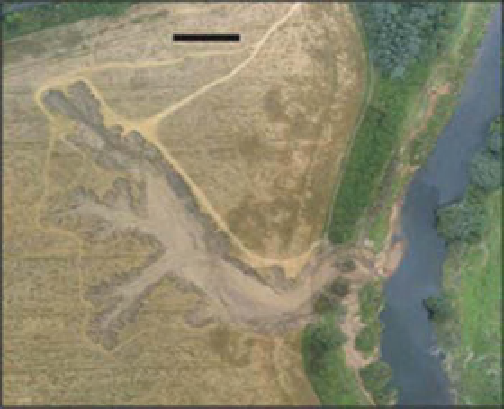
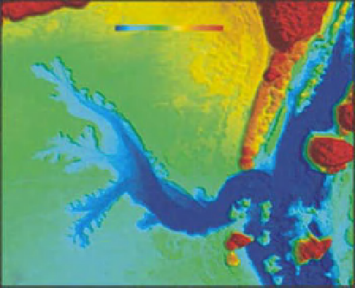
control. For example, Figure 8.7 presents a georeferenced
mosaic of a large erosional feature which was formed by a
mass failure in the wake of a flood near Durham, UK. The
figure is comprised of 72 images acquired at an altitude of
125 m with a small UAV manufactured by SmartPlanes
AB. in Sweden (see Figure 8.3b). The raw imagery was
acquired with a small format 7 megapixel Canon IXUS
camera and had a resolution of 5 cm per pixel. This UAV
25 m
25
30 35
Elevation (m)
(a)
(b)
Figure 8.7
Example of mosaics (a) and digital elevations (b) generated from hyperspatial imagery acquired from a UAV platform.
Search WWH ::

Custom Search