Geography Reference
In-Depth Information
0.4
0.35
0.3
0.25
0.2
0.15
0.1
0.05
0
3.5458
0.6 m
1 m
3 m
3.5459
3.5459
Time (s)
3.5459
5 m
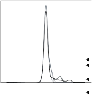
Figure 7.2b
Examples of a simulated 1-ns sampled green waveform for 60-cm (light grey), 1-m (grey), and 2-m clear water depth
(thin black line).
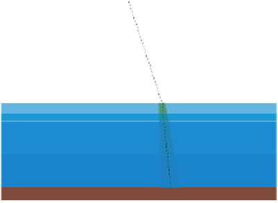
receiver. The Raman signal comes from inelastic interac-
tions between the green laser and the excitation energy
from the O:H bonds of water molecules directly below
the air-water boundary. Green laser-induced fluorescence
results as the bonds excite to a higher quantum state to be
backscattered while emitting the red wavelength. Both the
1,064- and 532-nm wavelengths for emission result from
the diffraction process of a single Nd:YAG 1,064-nm laser
pulse (Zege et al., 2004).
The use of both green and infrared wavelengths scanned
collinearly during a LiDAR survey provides a redundancy
and cross-validation of water-surface positioning, there-
fore it can help estimate water-bed positioning and depth
more accurately (Wozencraft and Millar, 2005). Indeed,
light celerity is different in air and water, the time budget
of laser beams inside these two media have to be precisely
determined as it highly conditions the ranging measures,
i.e., altimetric positions.
Even if green LiDAR can be used for terrestrial survey-
ing over riverbanks, the higher transmission of infrared
radiation in vegetation permits a better description of the
terrain under the vegetation.
In contrast to false infrared returns, if the green return
is noticeably weaker than the volume backscatter return it
may provide assistance when surface detections are incor-
rect due to land reflection or the presence of unexpected
targets occur, such as birds. Raman returns are accu-
rate regardless of wind speed and standing waves, while
wind speed weakens infrared surface returns. Therefore,
infrared and green Raman wavelengths should be coupled
together to reliably predict water surface (Gunther et al.,
1999; Allouis et al., 2010). In extremely shallow environ-
ments a more detailed interpretation of the Raman signal
may provide information about the water column depth,
water temperature, and composition, e.g. chlorophyll
(Burikov et al., 2004, Peeri and Philpot, 2007).
7.3 System parameters and capabilities:
examples
Up to 2009, four LiDAR systems have been used for
large bathymetry surveys: the SHOALS system (Canada),
the LADS system (Australia) (http://www.navy.gov.au/
Laser_Airborne_Depth_Sounder), the HawkEye system
(Sweden) and the EAARL system (US). As representative
systems, the two latter systems are detailed below.
7.3.1 Large footprint system:HawkEye II
HawkEye, originally designed by Saab Dynamics
(http://www.airbornehydro.com/hawkeyeii), is an air-
borne combined bathymetric and topographic LiDAR
system that is capable of surveying emergent and sub-
merged topography simultaneously using near-infrared
and green lasers. At present, the HawkEye system is
developed and manufactured by Airborne Hydrography
AB, a company formed from the original Saab group. The
HawkEye II sensor simultaneously collects bathymetric
measurements at 4 Khz and topographic measurements
at 64 kHz. The scanner pattern is generated by the
two axes of a servo-controlled scanner mirror, which
provides a constant incidence angle that is typically 20


Search WWH ::

Custom Search