Information Technology Reference
In-Depth Information
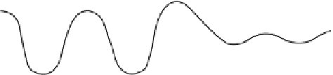
Fig. 1.10 Scheme of
tunneling of electrons
through a potential barrier
direction of particle moving
potential
barrier
wave function
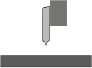
Fig. 1.11 Scheme of the
scanning tunneling
microscope
piezo-motor
V
DC
tip
test tip (<1nm)
tunnel current
substrate
substrate positioning
particles outside of the barrier, and, from that point on, the wave ceases to decay.
But since the wave function has not disappeared in the area outside of the barrier,
there exists a nonzero probability of finding the particle in this area, i.e., the particle
performs tunnel passage out of the potential well.
The scanning tunneling microscope is a system with an extremely thin needle tip
and the sample studied, to which constant voltage is applied (Fig.
1.11
). The
distance between the needle tip and the specimen is controlled by a piezo element.
If this distance becomes ~1 nm, tunnel current starts to flow between the tip and the
specimen which dramatically depends on the distance between the needle and the
specimen. Therefore, by moving the sample relative to the needle tip, the current
corresponding to each point of the sample surface can be measured. This relation-
ship corresponds to the contour of the surface.
The disadvantage of this microscope design is that the tunnel current strongly
depends on the distance between the needle tip and the specimen which complicates
the measurement of the current. For this reason another method to record the relief
of the surface is employed in tunneling microscopes. In this case a constant tunnel
current is maintained by the system which controls the piezo element by adjusting
the distance between the tip and the surface of the sample (Fig.
1.12
).
The creation of the scanning tunneling microscope was a revolutionary event,
which allowed to study the surface structure of solids and entities on such surfaces
while being able to discern individual atoms. One can get an idea about the