Environmental Engineering Reference
In-Depth Information
similar to the energy dissipation at stepped spillway, which has been applied for energy dissipation at
dams and has been studied by many scientists and engineers. The stepped spillway is designed to
increase the rate of energy dissipation (Chanson, 2001) and the design engineer must predict accurately
the energy dissipation. Following increase in discharge the flow on the stepped spillway develops from
nappe flow into skimming flow. A characteristic feature of the skimming flow is the high level of
free-surface aeration (Rajaratnam, 1990). Through the air-water interface, air is continuously trapped and
released, and the resulting two-phase mixture interacts with the flow turbulence yielding some intricate
air-water structure associated with complicated energy dissipation mechanisms (Chanson and Toombes,
2002, Carosi and Chanson, 2008).
Fig. 11.64
Defination of parameters for hydraulic jump for flow from slope to horizontal channel
Fig. 11.65
Step-pool system dissipated flow energy in hydraulic jumps and steps and the energy was transformed
into turbulence
The energy dissipation ratio at the stepped spillway
s
K is given by
EE
E
K
0
b
u
100%
(11.33)
sp
0
2
0
u
EH
g
(11.34)
0
2
u
2
Eh
cos
D
b
(11.35)
b
b
2
g
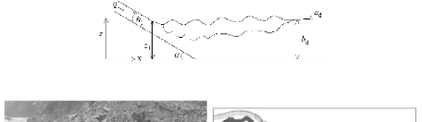
where
E
0
is the total specific energy of the flow at the top of the stepped spillway relative to a reference
plane; H is the height of the water surface on the top of the spillway relative to the reference plane;
u
0
is
the average velocity at the top of the spillway; D is the slope of the tangent of the spillway to the horizon;
E
b
is the total specific energy of the flow at the bottom of the stepped spillway relative to the reference
plane;
h
b
is the water depth at the bottom of the stepped spillway;
u
b
is the average velocity at the bottom
of the spillway.
Experimental studies have been done by scientists (Shvainshtein, 1999; Lu et al., 2006).


Search WWH ::

Custom Search