Environmental Engineering Reference
In-Depth Information
The design of any cap material must take into account future stability under varying flow conditions, e.g.,
flood flow, ice scour, wind induced currents, navigational propeller wash, and potential hydraulic changes
in the waterway. To account for these possible destabilizing conditions, the cap may need to be armored
with an engineered layer (e.g., coarse gravel or cobble sized material). For the Fox River, Wis., U.S.,
remediation Lue-Hing et al. (2001) recommended that the cap be designed to be stable under all anticipated
flow conditions, including the Standard Project Flood estimated by the U.S. Army Corps of Engineers,
which is almost twice as severe as a 100-year flood (1.8 times the 100-year flood). To be effective, a
conventional cap must remain in place until natural attenuation and/or fate processes eliminate the
potential for exposure and risk from contaminants in the underlying sediments. Given the potential
hydraulic difficulties in maintaining cap stability, Lue-Hing et al. (2001) noted that caps had primarily
been applied in bays and harbors—Hiroshima Bay, Japan; Long Island Bight, U.S.; Akoni Bay, Japan;
Hamilton Harbor, Canada: Pier 51 Ferry Terminal, Seattle, U.S.—and only a few rivers—St. Paul Waterway,
Washington, U.S. and St. Lawrence River, New York, U.S. The final design for the remediation PCB
contamination in the Fox River, Wis., U.S. will involve a combination of dredging and capping where caps
will be used in areas with lower PCB contamination and lower flow energy.
A cap layer of only 5-15 cm will generally isolate the bulk of contaminants from the benthic community
and overlying water. However, a minimum cap thickness of 15-30 cm is typical to provide a safety factor,
to ensure that the cap layer remains stable even if there is significant heterogeneity in placement thickness,
and to protect the overlying water from migration of water through the cap (Lue-Hing et al., 2001). A 15 cm
cap with the upper 10 cm compromised by bioturbation will reduce the steady state flux (diffusion) to the
overlying water by a factor of about 500, and a 30 cm cap with a 10 cm bioturbation layer gives a reduction
factor of about 1500 (Lue-Hing et al., 2001). Sand is commonly used as cap material, however, other cap
materials can also be used to satisfy specific objectives such as erosion protection and habitat enhancement.
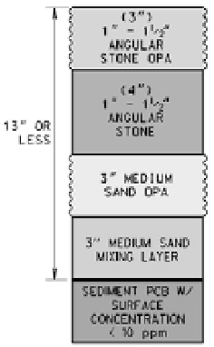
The cap design for the Little Lake Butte Des Morts project of the Fox River remediation is shown in
Fig. 9.26. This design includes 17.8 cm (7 in.) of 2.5-3.2 cm (1-1.25 in.) angular stone (7.5 cm [3 in.] as an
overplacement allowance) over 15 cm of medium sand (7.5 cm [3 in.] as an overplacement allowance).
Fig. 9.26
Cap Design for the Little Lake Butte Des Morts project of the Fox River remediation project, Wisconsin,
U.S. (figure provided by Steven Laszewski, Foth Infrastructure and Environment, Green Bay, WI)
If subaqueous capping is the selected technology (without dredging), the potential for cap loss and
re-exposure of deeper sediments needs to be addressed (NRC, 2001a). Caps can be repaired if needed at
relatively low cost.

Search WWH ::

Custom Search