Environmental Engineering Reference
In-Depth Information
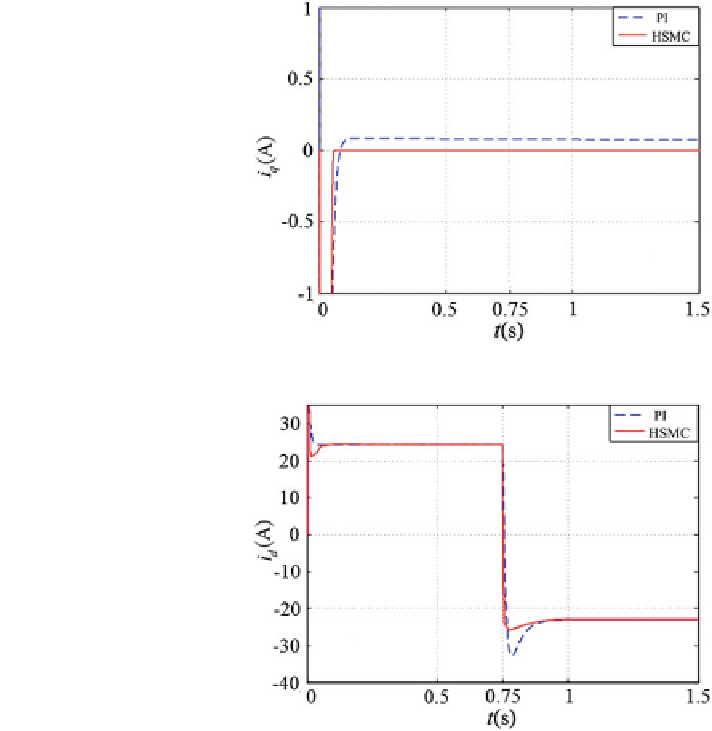
Fig. 3.8
i
q
in load current
change
Fig. 3.9
i
d
in load current
change
3.6.1 Step Changes in the Load Current
In this test, the load current is changed from 15A to -15A at the time t = 0.75 s. It
can be seen from Fig.
3.6
that the DC-link voltage with the TSM control can track
the given voltage and have lower ripple and faster convergence than that using PI
control. From Fig.
3.7
, it can be seen that the grid-side PWM converter works as a
rectifier with unity power factor and absorbs the energy from the power grid before
t = 0.75 s and works as an inverter with unity power factor and transfer the energy
to the power grid after t = 0.75 s. Figure
3.8
shows that the current in q-axis
converges to zero, and the TSM control has higher tracking accuracy. Figure
3.9
presents that the error of the current in d-axis with the TSM control strategy can
achieve lower ripples and faster convergence. The control signals for SMC and
TSMC control are shown in Figs.
3.10
and
3.11
. It can be seen that traditional
SMC signals exist chattering, but high-order TSM control signals are smooth.